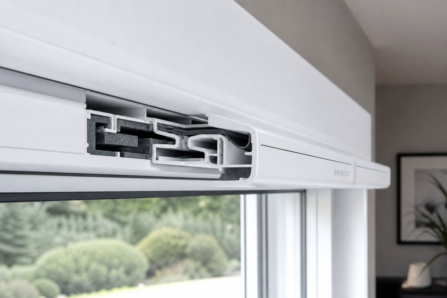
Acoustic trickle vents are specialized window ventilators that allow a controlled flow of fresh air into a building while significantly reducing the transmission of external noise. Unlike standard trickle vents, which use a simple open slot, these units incorporate internal baffles, labyrinth airflow channels, and sound-absorbing linings engineered to attenuate sound waves before they reach your living space.
That distinction matters more than most people realize. Every window is only as quiet as its weakest element, and a standard trickle vent slot punches a direct acoustic hole through an otherwise well-insulated facade. You could invest in high-performance double glazing, precision-engineered seals, and a robust frame, yet a single unattenuated vent opening can undermine the entire assembly's sound insulation.
The demand for acoustic trickle vents for noise reduction stems from a dual mandate that builders, architects, and homeowners all face. UK Building Regulations require background ventilation in habitable rooms, typically delivered through trickle vents in window frames. At the same time, properties near busy roads, railways, and flight paths must maintain acceptable indoor noise levels. Balancing those two obligations, letting air in while keeping noise out, is precisely the problem these vents are designed to solve.
Imagine sealing every gap in a boat, then drilling a small hole in the hull. Water finds that opening instantly. Sound behaves the same way. A standard trickle vent's straight-through slot offers virtually no resistance to airborne noise, creating an acoustic shortcut that bypasses your glazing, seals, and frame. In noise-sensitive environments, this difference between acoustic and standard trickle vents becomes impossible to ignore, especially at night when even moderate traffic noise disrupts sleep.
A single unattenuated trickle vent can reduce the overall sound insulation of a high-performance window by several decibels, effectively canceling out much of the acoustic benefit the glazing provides.
This article is structured for two audiences. If you are a homeowner wondering whether trickle vents let noise in and what you can do about it, you will find clear, practical guidance on assessment, selection, and installation. If you are a specifier, architect, or contractor navigating the intersection of Approved Documents F, E, and O, you will find the regulatory detail, acoustic metrics, and trade-off analysis needed to make confident specification decisions.
The journey starts inside the vent itself, where a surprisingly intricate internal architecture turns a compact plastic housing into an effective noise trap.
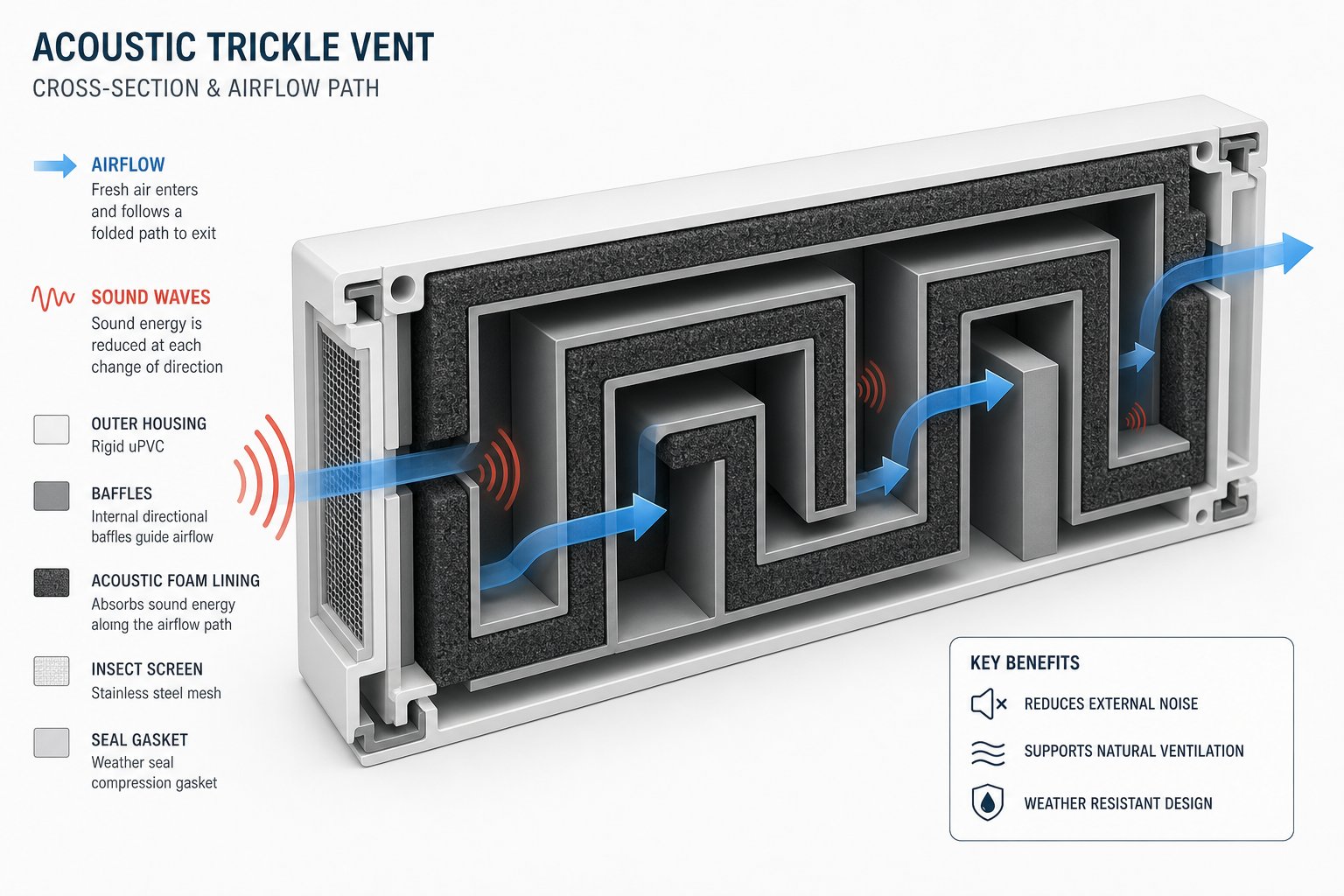
Picture shouting down a straight hallway versus shouting into a winding cave. In the hallway, your voice carries clearly to the other end. In the cave, every twist and turn absorbs a little more energy until only a muffled echo remains. That cave is essentially what sits inside an acoustic trickle vent, miniaturized into a compact housing no larger than your forearm.
Understanding how acoustic trickle vents work requires a look at three interconnected design features: the labyrinth airflow path that forces sound waves through repeated direction changes, the sound-absorbing materials that line those internal channels, and the baffle geometry that ties it all together. Each element plays a distinct role, and together they convert a simple ventilation slot into an effective noise trap.
The defining feature of an acoustic vent is its internal labyrinth, a folded air channel that extends the effective path length sound must travel within a compact housing. Instead of passing straight through a slot in a fraction of a second, incoming air is routed through a series of tight turns, switchbacks, and narrow chambers created by precisely positioned internal baffles.
Why does a longer, more convoluted path reduce noise? Every time a sound wave hits a surface and changes direction, a portion of its energy is reflected backward or scattered rather than continuing forward. The physics here mirrors what happens in HVAC duct silencer design, where elbow silencers combining directional change with absorptive lining achieve 5 to 15 dB of insertion loss per turn. Scale that principle down to a window vent with multiple internal direction changes, and you begin to see how significant cumulative attenuation becomes.
The acoustic baffle vent mechanism works because sound waves and airflow behave differently when confronted with obstacles. Air molecules are patient; they navigate around baffles, squeeze through narrow gaps, and eventually find their way to the interior side of the vent. Sound pressure waves, on the other hand, lose coherence and energy with each redirection. The result is that fresh air arrives indoors largely intact, while the noise riding along with it has been stripped of much of its power.
A well-designed labyrinth airflow path can achieve an effective internal channel length several times greater than the vent's physical depth. This is the key engineering trick: you do not need a vent as deep as a wall cavity to get meaningful sound reduction. By folding the path back on itself, manufacturers pack a long attenuation channel into a housing that still fits within a standard window frame or surface-mounted canopy.
Direction changes alone do not tell the full story. Lining the internal channels with absorptive materials adds a second, complementary attenuation mechanism. These linings, typically acoustic foam or fibrous inserts, work by converting sound energy into tiny amounts of heat through viscous friction as air molecules vibrate against and within the porous material.
As Titon's guide to acoustic trickle vents explains, these sound-absorbing materials disrupt and dampen sound waves as they pass through the vent, reducing noise levels before air reaches the indoor side. The absorptive lining is particularly effective against mid-to-high-frequency noise, the frequency range that includes human voices, birdsong, car horns, and the higher-pitched components of traffic roar.
The relationship between material thickness and frequency absorption is worth understanding. Thicker absorptive linings capture lower-frequency sounds more effectively because low-frequency waves have longer wavelengths that need more material depth to dissipate. Higher-frequency sounds, with their shorter wavelengths, are absorbed more readily even by thinner linings. This is why premium sound-absorbing trickle vent designs often use denser or thicker inserts: they extend the effective absorption range downward into the lower frequencies where traffic rumble and rail noise concentrate.
Crucially, these porous materials do not block airflow. Air passes through or around them with only modest resistance, which is why the vent can still deliver its required equivalent area for ventilation compliance. Sound energy, however, gets progressively absorbed with each centimeter of lined channel it traverses.
With those mechanisms in mind, it becomes obvious why a standard trickle vent offers virtually no noise reduction. A conventional slot vent is exactly what it sounds like: a straight-through opening cut into the window frame, covered by a simple internal flap and an external rain deflector. There are no direction changes, no absorptive linings, and no extended path length. Sound waves pass from the exterior to the interior with almost nothing to impede them.
Think of it as the difference between a locked door and an open doorway. The glazing and frame are the locked door, carefully engineered to block noise. The standard vent slot is an open doorway right next to it, letting sound walk straight through. The labyrinth design of an acoustic vent essentially replaces that open doorway with a long, padded, winding corridor that sound must struggle through.
The following table makes this contrast concrete:
| Feature | Standard Trickle Vent | Acoustic Trickle Vent |
|---|---|---|
| Airflow Path Type | Straight-through slot | Folded labyrinth channel with multiple switchbacks |
| Effective Path Length | Equal to frame depth (typically 30-70 mm) | Several times the frame depth due to folded routing |
| Number of Direction Changes | Zero | Multiple (typically 3 or more internal turns) |
| Absorptive Lining Present | No | Yes — acoustic foam or fibrous inserts line internal channels |
| Sealing and Gasket Quality | Basic weather flap | High-performance gaskets for enhanced acoustic and weather sealing |
| Typical Sound Reduction (Dne,w) | Negligible (often unmeasured) | Typically 25-45 dB depending on design complexity |
The difference in typical sound reduction is striking. Where a standard slot contributes almost nothing to the facade's acoustic defense, a well-engineered acoustic vent can deliver attenuation figures in the same general range as the glazing unit itself. This is what transforms the vent from the weakest link in the window assembly into a component that actively supports the overall noise-reduction strategy.
Of course, numbers on a comparison table only matter if you can trust them. The acoustic ratings printed on product spec sheets use specific metrics, and misunderstanding those metrics leads to incorrect product comparisons and, ultimately, disappointing real-world performance.
Spec sheets for acoustic trickle vents are packed with abbreviations that look almost identical yet mean very different things. Confuse one metric for another, and you could end up comparing products that were never tested the same way. Worse, you might select a vent that looks impressive on paper but underperforms in your actual window assembly. A few minutes spent understanding these ratings saves hours of frustration later.
The metric you will encounter most often on an acoustic trickle vent spec sheet is Dn,e,w, which stands for element-normalized level difference, weighted. Sounds complex? Here is the plain-English version: it measures how much noise a small building element, like a ventilator, blocks when tested in isolation under controlled laboratory conditions.
The key phrase is "element-normalized." Unlike metrics designed for full walls or complete windows, the Dn,e,w rating accounts for the fact that a trickle vent is a small component installed within a larger assembly. The test setup, governed by BS EN ISO 10140, places the vent in a standardized opening and measures the sound level difference between the source room and the receiving room, then normalizes the result to a reference absorption area. This isolates the vent's own acoustic contribution from the performance of the surrounding wall or window.
The "weighted" part of the rating simplifies frequency-dependent performance into a single number. In reality, the vent attenuates different frequencies by different amounts, as the labyrinth and absorptive linings discussed earlier are more effective at some pitches than others. The weighted single-number value compresses that complex frequency curve into one dB figure you can compare across products. It is useful shorthand, but it is also a simplification. Two vents with identical Dn,e,w ratings could perform quite differently at specific frequencies, which is why industry guidance from manufacturers like Titon recommends reviewing frequency response charts alongside the single-number rating for a fuller picture.
You may also see the notation written as Dne,w without the commas. As Brookvent clarifies, this is the current standard metric for acoustic vent performance, produced by testing the vent in isolation rather than within a frame assembly. An older metric, Dnt,Rw, tested the vent while installed in a frame, which blended the frame's own acoustic properties into the result. The modern element-normalized approach gives a more accurate representation of what the vent itself delivers. Higher Dn,e,w values indicate better sound reduction: a vent rated at 44 dB provides noticeably more attenuation than one rated at 35 dB.
If you have researched glazing or window performance, you will recognize Rw, the weighted sound reduction index. It is the standard metric for panels, glazing units, walls, and complete window assemblies. Rw describes how much sound a large, continuous element blocks, and it works well for those applications.
The problem arises when Rw is applied to small openable elements like trickle vents. A ventilator is not a panel. It has a tiny area relative to the surrounding facade, and it behaves acoustically in a fundamentally different way. Using Rw for a vent can produce misleading comparisons, because the metric was not designed to normalize for the small opening area and specific transmission characteristics of a ventilation slot. When you see Rw quoted for a vent rather than Dn,e,w, treat that number with caution. It may not be directly comparable to another product's Dn,e,w rating, even if both figures are expressed in decibels.
With these distinctions in mind, you can approach any acoustic trickle vent spec sheet guide with confidence. Here is a practical checklist to follow before making any product comparison:
Always compare acoustic vent performance using the same metric, the same test position, and the same equivalent area — mixing these variables makes any product comparison meaningless.
Armed with the right way to read these numbers, the next challenge is understanding why building regulations force you to care about them in the first place. Three UK Approved Documents converge on the same window opening, each pulling in a slightly different direction, and navigating their intersection is where specification decisions get genuinely complex.
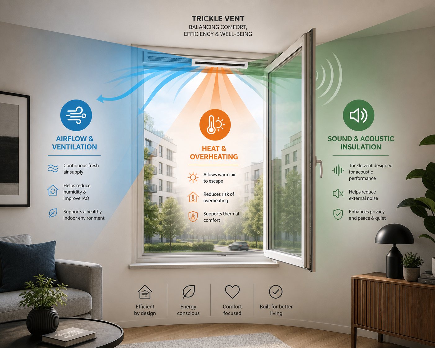
Three separate Approved Documents under UK Building Regulations each stake a claim on your window opening. One demands airflow. Another demands quiet. A third demands the ability to shed excess heat. Individually, each requirement is straightforward. Together, they create a design tension that makes acoustic trickle vents not just a nice upgrade but a genuine specification necessity in noise-sensitive locations.
Understanding these building regulations for acoustic trickle vents in the UK is essential whether you are a homeowner trying to figure out why your builder installed a particular vent type or a specifier juggling compliance across multiple regulatory documents. Here is how the three intersect, and why that intersection matters.
Approved Document F governs ventilation in buildings and sets out the requirements for maintaining adequate indoor air quality. For residential dwellings, this means every habitable room needs a defined pathway for background ventilation, the kind of continuous, low-level airflow that prevents condensation, dilutes indoor pollutants, and keeps air from becoming stale.
Trickle vents are the standard compliance pathway for meeting these Approved Document F trickle vent requirements. The regulation specifies minimum equivalent areas (EAs) for background ventilators based on room type and dwelling size. A bedroom might require a different EA than a kitchen or living room, but the principle remains the same: a measured amount of ventilation capacity must be permanently available, usually delivered through controllable vents installed in window frames.
Here is the critical limitation, though. Document F is exclusively concerned with airflow. It tells you how much ventilation you need and where to provide it, but it says nothing about the acoustic performance of the ventilator you install. A simple slot vent satisfies Document F just as easily as a sophisticated labyrinth-type unit. From a pure ventilation compliance standpoint, there is no regulatory distinction between the two. This gap is exactly where problems begin for properties in noisy environments.
Approved Document E addresses the resistance to the passage of sound. It sets minimum sound insulation performance standards for separating walls and floors in new-build residential developments, covering both airborne and impact sound transmission between adjacent dwellings.
While Part E focuses primarily on internal separation elements, its requirements connect directly to facade acoustic performance through BS 8233, the British Standard that provides guidance on acceptable internal ambient noise levels for different room types. Bedrooms, for example, require lower internal noise levels than living rooms, particularly during nighttime hours. When an acoustic assessment identifies that external noise sources, such as a nearby road or railway, will push internal levels beyond these recommended thresholds, the entire facade must deliver sufficient composite sound insulation to bring those levels down. Every component in that facade matters, including every trickle vent.
This is where the Approved Document E sound insulation vents connection becomes tangible. A specifier designing a facade to meet BS 8233 internal noise targets cannot ignore the ventilator. If the glazing unit achieves an Rw of 35 dB but the trickle vent sitting above it offers negligible attenuation, the facade's composite performance drops. The vent becomes the acoustic hole that Part E's broader noise-control objectives demand you close.
Approved Document O, introduced for new residential buildings, tackles overheating risk. It requires designers to demonstrate that homes will not overheat during warmer months, using either a simplified method or dynamic thermal modeling. One of its primary mitigation strategies is natural ventilation: openable windows, purge ventilation pathways, and cross-ventilation designs that allow excess heat to escape.
The Approved Document O overheating ventilation conflict emerges quickly in noise-sensitive locations. Document O pushes toward larger openable areas and greater ventilation capacity. In quieter settings, that is a straightforward design exercise. But when a site sits under an airport flight path or beside a busy A-road, opening windows wide enough to manage overheating exposes occupants to precisely the noise that the acoustic strategy was designed to exclude.
This creates a genuine dilemma. Increasing purge ventilation openings to satisfy overheating requirements can undermine the acoustic performance of the facade. Designers may need to increase the number of trickle vents, specify larger units, or supplement passive ventilation with mechanical systems, all of which affect acoustic performance calculations. The pressure Document O places on ventilation capacity ripples directly into vent selection decisions.
Imagine three people pulling on the same rope in different directions. Document F pulls toward adequate airflow. Document E pulls toward sound insulation. Document O pulls toward larger openings for heat dissipation. The window opening, and specifically the trickle vent installed in it, sits at the exact point where all three forces converge.
This is the core regulatory challenge that elevates acoustic trickle vents from a product category to a specification necessity. A standard slot vent can satisfy Document F's airflow demands easily. It cannot, however, maintain the facade's acoustic integrity required by Document E in noisy environments. And when Document O pushes for even more ventilation capacity, the acoustic challenge intensifies further.
The following table maps each Approved Document's primary concern, its specific requirement relevant to vents, and how acoustic trickle vents address the resulting tension:
| Approved Document | Primary Concern | Requirement Relevant to Vents | How Acoustic Trickle Vents Address It |
|---|---|---|---|
| Document F (Ventilation) | Indoor air quality and adequate background ventilation | Minimum equivalent areas (EAs) for background ventilators in habitable rooms | Deliver the required EA through labyrinth channels that maintain airflow while adding sound attenuation — satisfying ventilation mandates without acoustic compromise |
| Document E (Sound) | Resistance to the passage of sound between and within dwellings | Facade must support BS 8233 internal noise targets; every element including ventilators contributes to composite sound insulation | Provide tested Dn,e,w performance ratings that can be factored into facade acoustic calculations, preventing the vent from becoming the weak link in the assembly |
| Document O (Overheating) | Preventing overheating in new residential buildings | Sufficient purge and background ventilation capacity to mitigate excess heat, potentially requiring larger or additional openings | Offer higher-capacity units with maintained acoustic performance, or allow multiple vents to be specified without each one degrading the facade's noise-reduction strategy |
The design tension captured in this table is not theoretical. It plays out on real projects every day, particularly on urban sites where external noise levels are high and overheating risk is elevated by solar gain from surrounding hard surfaces. Specifiers working with these building regulations for acoustic trickle vents in the UK must balance all three demands simultaneously, and the only product category that resolves the conflict without resorting to full mechanical ventilation is the acoustic trickle vent.
Recognizing this regulatory landscape is one thing. Deciding whether your specific property or project actually requires acoustic-rated vents, or whether standard units will suffice, depends on a more practical question: how noisy is the environment outside your facade?
Not every property needs acoustic-rated ventilation. A farmhouse surrounded by open fields faces a very different noise environment than a flat overlooking a six-lane arterial road. The question "do I need acoustic trickle vents?" is not answered by looking at product catalogs. It is answered by stepping outside your front door, standing still, and honestly evaluating what you hear.
That informal assessment is actually the starting point of a more structured process used by acoustic consultants on every residential project in a noise-sensitive location. Here is how to apply a simplified version of that process to your own situation.
Your noise assessment for trickle vent selection starts with identifying the dominant noise sources affecting your property. The most common culprits are road traffic, railway lines, aircraft flight paths, industrial operations, and the general ambient hum of dense urban areas. Proximity matters enormously: a property fifty meters from a busy A-road experiences a fundamentally different noise climate than one five hundred meters away.
The benchmark for what constitutes acceptable indoor conditions comes from BS 8233:2014, the British Standard that sets recommended internal ambient noise levels for residential buildings. Its criteria reflect the principle that sleeping areas demand the lowest noise levels, while living spaces can tolerate slightly more. The BS 8233 internal noise levels for ventilation design are specific and measurable:
These figures come directly from BS 8233:2014 Table 4 and represent "good acoustic design" targets used by planning authorities across the UK. The practical implication is straightforward: if external noise at your facade is high enough that a standard vent allows internal levels to exceed these thresholds, you have a problem that only an acoustically rated vent — or a more substantial intervention — can solve.
In quieter suburban and rural settings, standard vents are perfectly adequate. If your property sits on a residential cul-de-sac, in a village away from major transport corridors, or in any location where external daytime noise levels are comfortably low, the small acoustic weakness of a standard slot vent simply does not matter. The gap between outside noise and the BS 8233 internal targets is large enough that even an unattenuated vent does not push internal levels beyond acceptable limits.
You will notice this intuitively. If you can sit in your garden and hold a normal conversation without raising your voice, if nighttime is genuinely quiet apart from the occasional passing car, then the external noise environment is unlikely to demand acoustic-rated ventilation. The money and complexity of specifying labyrinth-type units would deliver no perceptible benefit in these conditions.
The picture changes dramatically when external noise is persistent and elevated. Knowing when to use acoustic trickle vents comes down to recognizing specific high-risk scenarios:
Busy roads. Properties within roughly 50 to 100 meters of a well-trafficked A-road or any distance close to a motorway are exposed to continuous broadband traffic noise that standard vents transmit almost unimpeded. Nighttime traffic on these routes does not stop, and the 30 dB LAeq bedroom target becomes extremely difficult to achieve without acoustic-rated ventilation.
Railway lines. Rail noise presents a particular challenge. As research published in the International Journal of Environmental Research and Public Health documents, railway noise is intermittent, carries significant low-frequency energy, and produces peak events (LAmax) that can exceed the averaged noise level by 20 to 30 dB. A single freight train passing at 2 a.m. creates exactly the kind of sleep-disrupting peak event that the 45 dB LAmax criterion exists to prevent. Standard vents offer no defense against these spikes.
Airport flight paths. Properties beneath approach or departure corridors experience repeated high-intensity noise events throughout the day and, at some airports, well into the night. The combination of event frequency and event loudness makes acoustic ventilation a baseline requirement rather than an upgrade.
Dense urban environments. Even without a single dominant source, the cumulative noise of city traffic, delivery vehicles, construction, emergency sirens, and nightlife can produce facade noise levels that breach the BS 8233 thresholds through an unattenuated vent.
Honesty about limitations is just as important as understanding benefits. At very high external noise levels — directly alongside a motorway, immediately adjacent to a major rail line carrying freight traffic, or beneath a busy airport's primary flight path — acoustic trickle vents alone may be insufficient to achieve acceptable internal conditions. The labyrinth design and absorptive linings can only attenuate so much, and when facade noise levels are extreme, even a well-rated vent cannot close the gap between outside and the 30 dB nighttime bedroom target.
In these scenarios, supplementary solutions become necessary. BS 8233 assessments for highly exposed sites frequently specify mechanical ventilation with heat recovery (MVHR) systems that allow windows to remain permanently closed while maintaining air quality. Acoustic secondary glazing, purpose-built noise barriers, and careful building orientation all play roles in the most demanding projects. The acoustic vent remains a valuable component of the overall strategy, but it is one element rather than the entire solution.
Use this framework to determine the right ventilation approach for your property or project:
This decision framework gets you to the right product category. The next challenge is more subtle: understanding that every acoustic vent involves a fundamental trade-off between how much air it lets through and how much noise it blocks, a relationship that determines whether a single vent can satisfy both your ventilation and acoustic requirements simultaneously.
Here is the uncomfortable truth that product brochures rarely spell out: every decibel of noise reduction you gain through a labyrinth vent comes at a cost in airflow capacity. The same baffles, direction changes, and absorptive linings that strip energy from sound waves also create resistance that slows the movement of air. This is not a design flaw. It is fundamental physics, and understanding it is the difference between a specification that works on paper and one that works in practice.
The airflow vs noise reduction trickle vent trade-off sits at the heart of every acoustic vent selection decision, yet it is the topic most frequently glossed over in product literature. You deserve a clear explanation of why this tension exists and how to navigate it.
Before you can appreciate the trade-off, you need to understand equivalent area, the metric that quantifies a vent's airflow capacity. The Domestic Ventilation Compliance Guide defines equivalent area (EA) as the area of a sharp-edged circular orifice through which air would pass at the same volume flow rate, under an identical applied pressure difference, as the ventilator under consideration. In simpler terms, imagine replacing your vent with a perfectly round hole. The size of that hole that would let through the same amount of air is your vent's equivalent area.
EA is measured in square millimeters at a standardized pressure difference of 1 Pascal, and it provides a universal way to compare the ventilation performance of different products regardless of their physical shape or internal design. A vent rated at 4,000 mm² EA delivers the same airflow as a perfectly circular opening roughly 71 mm in diameter, no matter how complex its internal geometry might be.
Building regulations specify minimum EAs for different room types and dwelling sizes. As Titon's regulatory overview notes, typical total EA requirements range from 8,000 mm² for a one-bedroom dwelling to 15,000 mm² for a four-bedroom home. Each habitable room needs its own background ventilator contributing toward that total. Fall short of these minimums, and you fail to comply with Approved Document F, regardless of how impressively your vents perform acoustically.
This is why equivalent area matters so much in the context of acoustic trickle vent selection. The EA is not optional. It is a regulatory floor that every ventilator must meet.
Picture a garden hose with nothing inside it. Water flows freely. Now stuff the hose with sponge material and add several tight bends. The water still gets through, but the flow rate drops noticeably. The same principle governs what happens inside an acoustic vent. Increasing the labyrinth path length, adding more baffles, and lining channels with thicker absorptive material all improve sound attenuation, but they also create more resistance to airflow, reducing the achievable EA for a given vent size.
This means a vent with a higher acoustic rating may have a lower equivalent area. A compact unit designed to fit within a standard window frame has a fixed amount of internal volume to work with. Devoting more of that volume to longer labyrinth paths and denser acoustic linings leaves less effective cross-sectional area for air to pass through. The physics is non-negotiable: you cannot simultaneously maximize both airflow capacity and noise reduction within the same physical envelope.
The practical consequences are significant. A vent delivering a Dn,e,w of 42 dB might achieve an EA of only 2,500 mm², while a less acoustically ambitious unit rated at 33 dB might deliver 5,000 mm² EA from the same housing dimensions. If your room requires 5,000 mm² of background ventilation, the higher-performing acoustic vent cannot do the job alone. You would need two of them, or you would need to step up to a physically larger unit that accommodates both the extended labyrinth and the required airflow cross-section.
This is the trade-off that catches specifiers off guard. Selecting the vent with the highest Dn,e,w rating on the market sounds like the safest choice, but if that vent cannot deliver sufficient EA for your room, you have solved the noise problem while creating a ventilation compliance failure.
The practical specification process for balancing ventilation and acoustic performance follows a logical sequence, though the execution can become the most challenging aspect of the entire facade design in high-noise environments.
Start with the required EA. Determine the minimum equivalent area your room or dwelling needs from Approved Document F. This is your non-negotiable ventilation baseline. Every vent you consider must meet or exceed this figure.
Determine the required acoustic performance. Use the noise assessment approach outlined in the decision framework — external noise levels, proximity to sources, BS 8233 internal targets for the room type — to establish the minimum Dn,e,w your vent must achieve. This is your acoustic baseline.
Find a product that satisfies both constraints simultaneously. Search for a vent whose published EA meets your ventilation requirement and whose Dn,e,w meets your acoustic requirement, both verified at the same operational setting. This is where the challenge becomes real. A vent's EA and Dn,e,w are often quoted at the same test configuration, but always confirm that the acoustic rating applies at the EA you need, not at a more restrictive setting that reduces the opening size.
When a single vent cannot satisfy both constraints, you have three options: specify a physically larger vent that provides more internal volume for both the labyrinth and the airflow path; install multiple smaller acoustic vents that collectively meet the EA requirement while each contributing its acoustic performance; or, in the most demanding cases, supplement passive ventilation with a mechanical system that removes the need for vents to carry the entire airflow burden.
Acoustic performance and ventilation capacity must be specified together, never in isolation — selecting a vent for its sound rating without verifying its equivalent area, or vice versa, guarantees a compliance failure on one side of the equation.
This balancing act becomes especially consequential when you move from the abstract specification process to the concrete realities of installation. Whether you are designing a new-build facade or retrofitting existing windows, the physical constraints of your window frame determine which products can actually deliver the EA and acoustic rating your project demands.
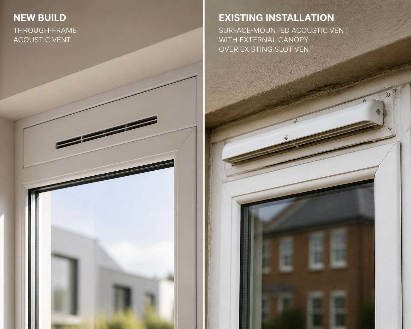
A brand-new apartment block on a flight path and a 1990s semi-detached house beside a railway line share the same acoustic problem, but the path to solving it looks completely different. In one scenario, the acoustic vent is specified at the drawing-board stage and integrated seamlessly into a purpose-designed window system. In the other, a homeowner is standing in a bedroom at midnight, listening to traffic drone through a slot vent that came with replacement windows installed three years ago. Both need effective noise attenuation. Neither can approach the problem the same way.
This gap between new-build acoustic vent specification and retrofit acoustic trickle vents for existing windows is one of the least discussed topics in the ventilation space, yet it shapes every practical decision, from product selection to installation method to whether you need a professional fitter or can tackle the job yourself.
In new-build projects, acoustic trickle vents are specified during the design stage, long before the first window frame arrives on site. This is an enormous advantage. The architect, acoustic consultant, and window system supplier can coordinate every element of the facade simultaneously, ensuring that vent selection aligns with the glazing unit's Rw rating, the frame system's depth, and the overall composite acoustic performance target derived from the BS 8233 noise assessment.
The practical benefit is straightforward: when the window system is designed from the outset to accommodate an acoustic vent, the frame profile includes sufficient depth and slot geometry for a labyrinth-type unit. There is no need to compromise on internal channel length, baffle count, or absorptive lining thickness because the available space was planned from day one. The vent integrates natively into the frame, the external canopy sits flush with the weather detailing, and the whole assembly arrives on site as a coordinated, tested system.
Selecting frame systems that accommodate acoustic vents without modification eliminates one of the most common specification headaches. Some window profiles are designed with deeper head sections specifically to house acoustic inserts, while others offer modular vent housings that clip into standardized slots. When you choose a system with native acoustic vent compatibility, you avoid the awkward discovery, partway through procurement, that the specified vent physically cannot fit the chosen frame. On noise-sensitive sites, this compatibility check should happen before the window system is finalized, not after.
New-build specification also benefits from the ability to coordinate multiple vents across a facade. If a single acoustic vent cannot deliver both the required equivalent area and the target Dn,e,w for a particular room, the designer can distribute the ventilation load across two or more vents integrated into different window units on the same elevation. This flexibility simply does not exist in most retrofit situations.
Retrofit is where things get real for most homeowners. You already have windows. They might be perfectly good uPVC casements installed within the last decade, and the glazing performs well. But the trickle vent slot, a simple straight-through opening cut into the top of the frame, transmits every passing truck, every late-night motorcycle, every early-morning delivery van directly into your bedroom. Sound familiar?
The challenge with retrofitting acoustic trickle vents to existing windows is that the frame was never designed to house a labyrinth-type unit. Standard trickle vent slots are typically shallow, often only 12 to 15 mm deep in the frame, with a narrow rectangular opening that matches the profile of a basic slot vent. An acoustic vent, with its extended internal airflow path and baffled chambers, needs more depth. If the existing slot cannot accept a deeper insert, the through-frame approach that works so elegantly in new-build projects simply is not viable.
Before purchasing any retrofit product, you need to check several critical dimensions and compatibility factors:
When the existing frame slot genuinely cannot accept a deeper acoustic unit, and that is often the case, surface-mounted solutions become the practical pathway forward.
Imagine you cannot go deeper into the frame. Instead, you go outward. Surface-mounted acoustic trickle vents attach to the interior face of the window frame, covering the existing slot and housing the labyrinth airflow path within an external body that projects slightly from the frame surface. An external canopy covers the outdoor side, providing weather protection while allowing air to enter the labyrinth channel.
This configuration is fundamentally different from through-frame vents. A through-frame unit sits entirely within the depth of the window profile, invisible except for the internal and external grilles. A surface-mounted unit, by contrast, is visible as a slim housing on the inside of the frame and a canopy on the outside. The trade-off is aesthetic rather than functional: the vent may be slightly more noticeable, but it delivers the same labyrinth attenuation and absorptive lining benefits as an integrated unit.
For retrofit projects, surface-mounted designs offer several practical advantages. They do not require modifying the frame slot beyond its original dimensions. They can be installed on uPVC, timber, and aluminum frames alike, provided the mounting surface is flat and the fixings are appropriate for the frame material. And they typically come as complete kits with internal housing, external canopy, fixings, and sealing strips, making installation more straightforward than frame modification.
Suppliers like Shengxin Aluminium offer window trickle vent ranges that include surface-mounted and canopy-design options compatible with uPVC passive ventilation systems, with tested airflow and acoustic data published alongside the product specifications. This kind of product range is useful for both architects specifying new-build systems who need verified EA and Dn,e,w figures for their facade calculations, and contractors handling retrofit projects who need units that fit existing frame geometries without structural modification.
The following table summarizes the key differences between new-build and retrofit installation scenarios to help you identify which approach applies to your project:
| Factor | New-Build Specification | Retrofit Installation |
|---|---|---|
| Integration Method | Through-frame, designed into the window system from the outset | Surface-mounted over existing slot, or slimline insert if frame depth allows |
| Typical Vent Types Available | Full range: through-frame labyrinth units, modular acoustic inserts, integrated canopy systems | Surface-mounted acoustic units with external canopy; slimline frame-fitted vents where slot geometry permits |
| Installation Complexity | Low — vent is factory-fitted or installed as part of the window assembly on site | Moderate — requires accurate measurement of existing slot, frame depth checks, and potential canopy fitting |
| Professional Fitting Recommended? | Handled by the window installer as standard | Recommended for acoustic units, especially where frame modification or reinforcement assessment is needed |
| Design Coordination | Vent performance coordinated with glazing, frame, and facade acoustic model | Vent selected to match or improve upon the existing window's acoustic performance without full facade redesign |
One detail worth highlighting: whether you are working on a new-build or a retrofit, the acoustic vent is never performing in isolation. It sits within a window assembly comprising glazing, frame, seals, and hardware, and the overall noise reduction you experience indoors depends on how all of those elements work together. A high-performing vent installed in a window with deteriorated seals or single-pane glazing will not deliver the quiet room you are expecting. That relationship between the vent and the rest of the window system is where the specification process either succeeds or quietly falls apart.

You could install the highest-rated acoustic trickle vent on the market and still hear traffic rumble through your bedroom wall. That is not a contradiction. It is the predictable result of treating the vent as a standalone product rather than as one component within a larger acoustic system. A window is not a single element. It is a composite assembly of glazing, frame, seals, hardware, and ventilator, and the noise you hear indoors is governed by whichever piece performs worst.
This weakest-link principle is the single most important concept in whole-window acoustic performance, yet it is routinely ignored during product selection. Homeowners fixate on glazing thickness. Specifiers focus on Dn,e,w ratings for the vent. Both miss the bigger picture: every component must pull its weight, or the one that does not will drag the entire assembly down to its level.
Imagine spending generously on a premium front door lock while leaving a ground-floor window wide open. That is essentially what happens when you install a vent rated at 42 dB Dn,e,w into a window with single-pane glazing achieving an Rw of 25 dB, or into a frame with deteriorated rubber seals that have shrunk and cracked over the years.
The physics is unforgiving. As Commercial Acoustics explains, the biggest acoustic losses rarely come through the glass itself — they come through framing connections and unsealed joints. A 1/8-inch unsealed gap can leak as much noise as a hole the size of a fist. Sound energy always finds the path of least resistance, and it will exploit every weakness in the assembly regardless of how well other components perform. A vent rated at a high Dn,e,w installed in a window with poor glazing performance or deteriorated seals delivers no meaningful benefit, because the noise simply bypasses the vent entirely and enters through the weaker element.
This is why acoustic consultants and experienced specifiers treat the window as a complete system rather than a collection of independent parts. The overall sound insulation of the assembly is not an average of its components. It is disproportionately influenced by the weakest link. Upgrade one element without addressing the others, and you are pouring money into a solution that cannot deliver what the numbers on the spec sheet promise.
For homeowners, the practical takeaway is clear: before investing in an acoustic vent, assess the condition of your entire window. Are the glazing seals intact? Is the frame free of warping or gaps? Does the opening mechanism close tightly without visible daylight around the edges? If any of these checks reveal problems, fixing the seals or upgrading the glazing should come before — or at least alongside — replacing the vent.
So how do you ensure the vent does not become either the weak link or an over-engineered expense? The answer lies in matching the vent's acoustic performance to the glazing and frame ratings of your window system.
Start with the Rw of your glazing unit. A standard double-glazed sealed unit might achieve an Rw of around 29 to 32 dB. A laminated acoustic glazing unit with an asymmetric pane configuration could reach 35 to 40 dB or higher. The overall window assembly rating, which factors in the frame and seals alongside the glass, will typically be a few decibels lower than the glazing unit alone.
Your vent selection should target a Dn,e,w value that sits within a similar performance range as the overall window assembly. If your window achieves a composite Rw of 32 dB, specifying a vent at 45 dB Dn,e,w is technically impressive but practically wasteful — you are paying for acoustic headroom the rest of the window cannot use. Conversely, pairing that same 32 dB window with a vent rated at only 25 dB Dn,e,w means the vent becomes the weakest link in the window sound insulation, pulling the composite performance below what the glazing alone could deliver.
The ACT Acoustics facade calculation guide provides a practical reference table that matches required free-field sound reduction to the minimum window Rw and trickle vent Dn,e,w values needed across different window sizes. For example, a facade requiring 25 dB of composite reduction with a 2 m² window needs a window Rw of approximately 23 dB paired with a vent Dn,e,w of around 29 dB. Scale that requirement up to 35 dB of composite reduction, and you need a window Rw of approximately 33 dB alongside a vent Dn,e,w of 39 dB. The pattern is consistent: as the facade performance demand rises, both the glazing and the vent must step up proportionally. Neither can compensate for the other's shortfall.
The general rule of thumb emerging from that data is that the vent's Dn,e,w typically needs to exceed the window's Rw by roughly 6 dB to avoid becoming the limiting element, though the exact relationship shifts with window area. Larger windows mean the glazing occupies a greater proportion of the facade, so the vent's relative acoustic contribution changes. This is precisely why specifiers need to calculate rather than guess.
For architects and acoustic consultants working on noise-sensitive projects, vent selection is not a standalone exercise — it is embedded within a facade composite acoustic performance calculation that models every element proportionally.
The principle is straightforward even though the mathematics can be involved. A facade is treated as a composite element comprising areas of different acoustic performance: the opaque wall, the glazing, the frame, and the ventilator. Each component contributes to the overall transmission loss based on two factors — its individual sound insulation performance and its area relative to the total facade. A small element with poor performance can disproportionately degrade the overall result because sound energy transmitted through a weak spot is not diluted by the stronger areas around it. It adds directly to the total sound entering the room.
This is why the vent, despite occupying only a tiny fraction of the facade area, can have an outsized negative impact. A ventilator with an effective open area of a few thousand square millimeters seems negligible compared to a 4 m² window and several square meters of surrounding brickwork. But if that small opening offers substantially less sound insulation than the glazing, it transmits a disproportionate share of the total noise energy reaching the room interior. The composite performance of the entire facade drops as a result.
To avoid this outcome, the specification process should follow a disciplined sequence. Here are the key steps for holistic vent selection that prevents the ventilator from undermining the rest of the facade:
This sequence ensures no single component is selected in a vacuum. The glazing, frame, seals, and ventilator are treated as parts of one interdependent system, and each specification decision is informed by the others. Skip any step, and you risk either wasting budget on over-specified components or creating an acoustic weak point that renders the rest of the investment ineffective.
The discipline of this process also reveals when the numbers simply will not work — when no commercially available vent can simultaneously deliver the required EA and Dn,e,w within the physical constraints of the chosen window system. Recognizing that ceiling early saves time, money, and the disappointment of a facade that underperforms against its design intent. It is at this decision point that the specification shifts from product selection to evidence-based engineering judgment.
Every principle explored throughout this guide converges on a single objective: choosing the right acoustic trickle vent for your specific situation, backed by evidence rather than assumptions. The labyrinth physics, the regulatory intersections, the airflow trade-off, the whole-window system thinking — none of it matters if the final product decision is driven by guesswork, habit, or whichever box happens to be on the shelf at the builder's merchant.
Confidence in this process comes from working methodically. You do not need an acoustics degree. You do need a willingness to ask the right questions, demand the right data, and refuse to accept vague performance claims dressed up in technical-sounding language.
The word "acoustic" on a product label is not a performance guarantee. Any manufacturer can call a vent acoustic. What separates a genuinely engineered noise-attenuating ventilator from a standard slot vent with a marketing upgrade is one thing: independently tested performance data.
As discussed in the metrics chapter, the figure you need is Dn,e,w — the element-normalized level difference, weighted — tested to BS EN ISO 10140 by an accredited laboratory. This is the metric designed specifically for small building elements like ventilators, and it isolates the vent's own acoustic contribution from the surrounding structure. A product spec sheet quoting this value, referencing the test standard, and specifying whether the rating applies in the open or closed position gives you something concrete to compare. A brochure that simply says "reduces noise" or "acoustic grade" without supporting data gives you nothing.
Third-party testing reports from bodies such as Sound Research Laboratories or BRE provide the most reliable performance evidence. These reports typically break down attenuation by frequency band, showing how the vent handles low-frequency traffic rumble differently from mid-range speech frequencies or high-pitched mechanical noise. That frequency detail matters — two vents with identical single-number Dn,e,w ratings can perform quite differently against the specific noise source affecting your property. Demand the full picture, not just the headline number.
The same scrutiny applies to equivalent area. A claimed EA value without a test certificate is an estimate at best. Verified EA figures, tested at a standardized 1 Pa pressure difference, confirm that the vent will actually deliver the airflow your room needs for Approved Document F compliance. Without that verification, you are trusting the label rather than the evidence.
The acoustic trickle vent selection guide that emerges from this article is not a single recommendation. It is a decision path — a sequence of assessments that leads you from your external noise environment to a specific, justified product choice. Each step builds on the one before it, and skipping any of them risks a mismatch between what you install and what your project actually demands.
Here is the complete sequence, distilled into a numbered action plan for specifying acoustic trickle vents for projects of any scale:
This sequence applies equally to a homeowner choosing a retrofit vent for a bedroom window and to an architect specifying hundreds of units across a residential development. The scale changes; the logic does not.
Knowing how to choose acoustic trickle vents means little if you cannot find suppliers who actually publish the data you need to make informed decisions. The industry has improved significantly in recent years, but not all manufacturers are equally transparent about tested performance figures.
When evaluating potential suppliers, look for these specific data points published openly alongside each product:
Suppliers who provide this level of detail demonstrate confidence in their products and respect for the specifier's decision-making process. Shengxin Aluminium's trickle vent product range illustrates this approach well — their product pages present tested airflow data, sound-reduction ratings, weather performance specifications, and custom project configuration options in a format that architects, contractors, and window system suppliers can work with directly. That transparency is exactly what evidence-based specification demands: concrete numbers you can plug into your facade calculations, not marketing adjectives you have to take on faith.
For homeowners navigating a simpler decision, the same principle applies at a smaller scale. If a supplier cannot tell you the Dn,e,w and EA of the vent they are recommending, that gap in information is itself a data point — and not a reassuring one.
The acoustic trickle vent is a small component that solves a large problem. It sits at the intersection of ventilation compliance, noise control, overheating management, and whole-window acoustic performance. Selecting one with confidence means respecting that complexity, following the evidence, and treating every spec sheet number as a claim that requires verification. Do that, and the labyrinth inside the vent does exactly what it was engineered to do: let air in and keep noise out.
Standard trickle vents do let noise in because they use a straight-through slot with no internal resistance to sound waves. This open pathway acts as an acoustic shortcut that bypasses your glazing and frame, allowing external noise to enter almost unimpeded. Acoustic trickle vents solve this by routing air through a folded labyrinth channel lined with sound-absorbing materials, forcing sound waves through multiple direction changes that strip away energy before it reaches your room. The difference in noise transmission between a standard slot vent and a labyrinth-type acoustic vent can be significant — with acoustic units typically achieving Dn,e,w ratings between 25 and 45 dB depending on design complexity.
Acoustic trickle vents work through two complementary mechanisms housed inside a compact unit. First, a labyrinth airflow path forces incoming air through multiple tight turns and switchbacks created by internal baffles. Each direction change causes sound waves to lose energy through reflection and scattering, while air molecules navigate around obstacles and continue flowing. Second, the internal channels are lined with sound-absorbing materials such as acoustic foam or fibrous inserts that convert remaining sound energy into tiny amounts of heat through viscous friction. Together, these features can extend the effective internal path length to several times the vent's physical depth, delivering substantial noise reduction without blocking ventilation airflow.
Dn,e,w (element-normalized level difference, weighted) is the correct metric for comparing acoustic trickle vents. It measures how much noise a small building element like a ventilator blocks when tested in isolation under lab conditions governed by BS EN ISO 10140. Rw (weighted sound reduction index), by contrast, is designed for large continuous elements such as glazing panels, walls, and complete window assemblies. Applying Rw to a small openable vent can produce misleading results because the metric was not designed to normalize for the tiny opening area and specific transmission characteristics of a ventilation slot. When comparing products, always confirm the spec sheet quotes Dn,e,w, check whether the value is for the open or closed position, and verify the equivalent area at which testing was conducted.
Yes, retrofitting acoustic trickle vents to existing windows is possible, though the approach differs from new-build installation. The main challenge is that most existing window frames were designed for shallow standard slot vents and may lack the depth needed for a full labyrinth-type insert. Surface-mounted acoustic vents offer the most practical retrofit solution — they attach over the existing vent slot and house the labyrinth airflow path within an external body that projects slightly from the frame. Before purchasing, measure your existing slot dimensions, check the frame depth at the head section, verify external canopy clearance, and identify any internal reinforcement in uPVC profiles. Suppliers like Shengxin Aluminium offer surface-mounted and canopy-design options compatible with uPVC frames, with published airflow and acoustic test data to support selection.
Balancing airflow and noise reduction is the central trade-off in acoustic vent selection. The same baffles and absorptive linings that attenuate sound also restrict airflow, meaning a vent with a higher Dn,e,w rating typically delivers a lower equivalent area (EA). Start by identifying the minimum EA your room requires under Approved Document F for ventilation compliance. Then determine the minimum Dn,e,w needed based on your external noise environment and BS 8233 internal noise targets. Finally, find a product that satisfies both constraints at the same operational setting. If no single vent meets both requirements, consider installing multiple smaller acoustic vents, specifying a physically larger unit, or supplementing with mechanical ventilation to share the airflow burden.



 serviço on-line
 0086 136 3563 2360
 sales@sxalu.com
 +86 136 3563 2360
 português
 English
 français
 Deutsch
 русский
 español
 العربية
 ไทย
ไทย Việt
Việt Українська