Ever wondered what keeps your smartphone from overheating during a long gaming session? Or how LED lights stay cool despite running for hours? The answer often lies in a deceptively simple component: the aluminum extrusion heat sink. This thermal management workhorse quietly protects billions of electronic devices worldwide, yet most engineers only scratch the surface when it comes to understanding how these heat dissipators actually work.
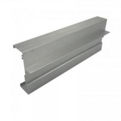
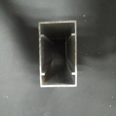
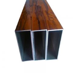
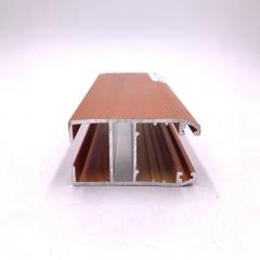
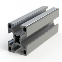
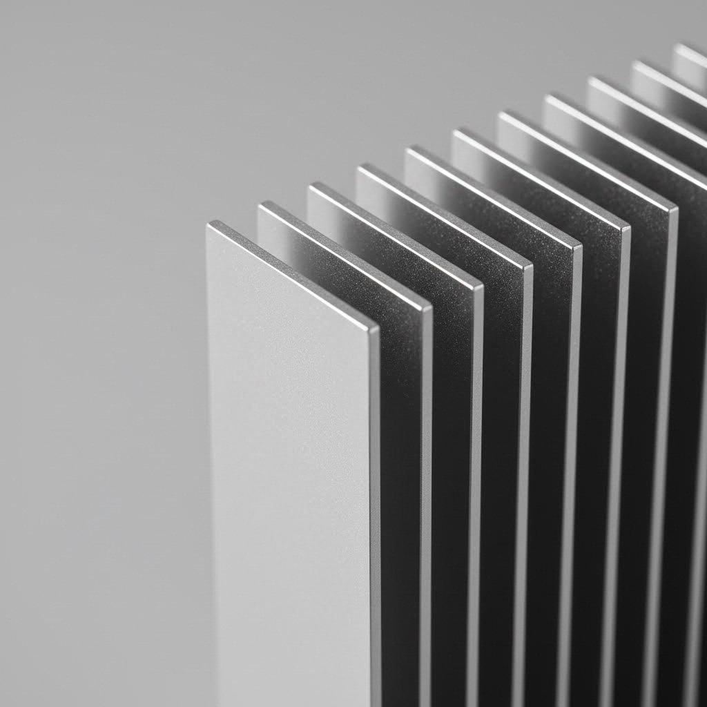
An aluminum extrusion heat sink is a thermally conductive component created by forcing heated aluminum billets through precision-engineered dies. This process produces finned profiles specifically designed to maximize surface area for heat dissipation. The result? A lightweight, cost-effective solution that transfers heat away from critical components and releases it into the surrounding air.
When you're asking "what are heat sinks made of," aluminum consistently tops the list—and for good reason. This metal delivers an exceptional balance of thermal performance, manufacturability, and affordability that other materials simply can't match.
Consider these engineering advantages:
With thermal conductivity of 205 W/m·K, aluminum transfers heat efficiently while weighing 60% less than copper—making it the optimal choice when balancing thermal performance against weight and cost constraints.
Why do aluminum heat sink designs feature those distinctive fins? It comes down to surface area. Heat transfer occurs at the interface between the heatsink and surrounding air. By increasing this surface area through carefully designed fins, extruded profiles dramatically improve heat dissipation rates.
The extrusion process itself is remarkably elegant. Aluminum billets are heated and then forced through custom-designed dies using hydraulic pressure. This creates continuous profiles with consistent cross-sections—perfect for producing the intricate fin patterns that define modern thermal management solutions.
Whether you're designing cooling for consumer electronics, automotive power systems, or industrial automation equipment, understanding these fundamentals transforms you from a basic specifier into someone who can truly optimize thermal performance. An alu heatsink isn't just a commodity part—it's an engineered solution where material science, manufacturing precision, and thermal physics converge.
Throughout this guide, you'll discover the specification-ready knowledge that separates successful thermal designs from costly failures: alloy selection strategies, fin geometry optimization, extrusion constraints, and the secondary operations that transform raw profiles into finished components.
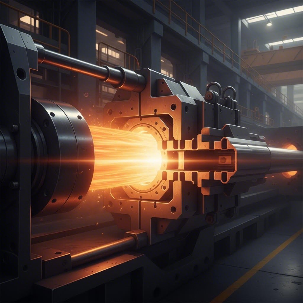
Understanding how an extruded heat sink transforms from raw material to finished component gives you a significant advantage when specifying thermal solutions. Unlike the thermoplastic extrusion process used for polymer-based products, aluminum heat sink extrusion demands precise temperature control, immense pressure, and specialized tooling. Let's walk through each stage of this manufacturing journey.
The process begins with a cylindrical aluminum billet—essentially a solid log of aluminum alloy, typically 6063 or 6061. Here's how that raw material becomes a precision thermal management component:
Step 1: Billet Preparation and Heating
Before anything can happen, the aluminum billet must reach the optimal temperature for extrusion. Operators heat billets to approximately 900°F (482°C)—roughly 400-500°C. At this temperature, the aluminum becomes malleable enough to flow through the die while maintaining structural integrity. Temperature control is critical: too cold, and the material won't flow properly; too hot, and you risk surface defects or compromised mechanical properties.
Step 2: Hydraulic Pressing Through Custom Dies
Once heated, the softened billet enters the extrusion press container. A powerful hydraulic ram then forces the aluminum through a hardened steel die—imagine squeezing toothpaste through a shaped opening, but with thousands of tons of pressure. The extruded aluminum heat sink material emerges from the die with the exact cross-sectional profile engineered into the tooling, whether that's a simple flat-back design or complex heatsink extrusion profiles with dense fin arrays.
Step 3: Cooling and Stretching
As the extruded aluminum heatsink profile exits the die, it travels along a runout table where controlled cooling begins. The profile then undergoes stretching—a process that straightens the extrusion and relieves internal stresses. This step ensures dimensional accuracy and prevents warping that could compromise thermal contact with heat-generating components.
Step 4: Cutting to Length
Finally, the continuous extrusion is cut to specified lengths using precision sawing equipment. These cut pieces then move to secondary operations for any additional machining, drilling, or surface treatments required by the application.
The die is where engineering intent meets manufacturing reality. Every detail of your heat sink extrusion—fin height, spacing, base thickness, and overall geometry—originates in this hardened steel tool. Die design directly impacts thermal performance by determining:
Here's what many specifications overlook: press tonnage fundamentally determines what's achievable. The hydraulic force available dictates both the size and complexity of profiles that can be produced.
| Press Tonnage Range | Typical Capabilities | Heat Sink Applications |
|---|---|---|
| 500-1500 tons | Smaller, simpler profiles | Consumer electronics, LED lighting |
| 1500-3500 tons | Medium complexity, moderate size | Power electronics, telecom equipment |
| 3500-5500+ tons | Large, complex profiles with high extrusion ratios | Industrial equipment, high-power applications |
As industry experts note, higher tonnage enables complex, thin-walled, multi-voided profiles that would be impossible on smaller presses. A demanding extruded heat sink with intricate fin geometry and tight tolerances requires substantial force to ensure aluminum fills every detail of the die completely and uniformly.
The extrusion ratio—how much the billet cross-section reduces through the die—also matters for thermal performance. Higher ratios, achievable with greater press tonnage, often produce better grain structure and mechanical properties in the finished profile.
Understanding these manufacturing fundamentals helps you specify realistic designs. When you know that a 6:1 fin height-to-gap ratio pushes standard extrusion limits, or that your complex profile demands a high-tonnage press, you can make informed decisions about geometry, tooling investments, and supplier selection.
You've seen both alloy numbers on datasheets—6063 and 6061—but which one actually belongs in your thermal design? This question trips up even experienced engineers, yet the answer dramatically impacts both thermal performance and manufacturing success. Let's cut through the confusion and examine what really matters when selecting aluminium heat sink material.
Both alloys belong to the 6000 series aluminum family, meaning they share an aluminum-magnesium-silicon composition. However, subtle differences in their chemical makeup create significant performance variations that matter for thermal management.
6063-T5 has earned its reputation as the go-to aluminum heatsink material for good reason. With thermal conductivity of approximately 200 W/m·K, it efficiently transfers heat away from components. But here's what makes it truly shine: exceptional extrudability. This alloy flows smoothly through complex dies, enabling the intricate fin geometries that maximize surface area for heat dissipation.
6061-T6 offers a different value proposition. Its thermal conductivity of 170 W/m·K is approximately 15% lower than 6063. However, 6061 delivers superior mechanical strength and hardness—critical when your heatsink aluminium must handle structural loads or resist mechanical stress.
| Property | 6063-T5 | 6061-T6 | Winner for Heat Sinks |
|---|---|---|---|
| Thermal Conductivity | 200 W/m·K | 170 W/m·K | 6063-T5 |
| Tensile Strength | 241 MPa | 310 MPa | 6061-T6 |
| Yield Strength | 214 MPa | 276 MPa | 6061-T6 |
| Brinell Hardness | 73 | 95 | 6061-T6 |
| Extrudability | Excellent | Good | 6063-T5 |
| Anodizing Quality | Superior finish | May show streaks | 6063-T5 |
| Relative Cost | Lower | Higher | 6063-T5 |
So when does each alloy make sense? The decision framework is more straightforward than you might expect.
Choose 6063-T5 when:
Choose 6061-T6 when:
Here's a practical insight: for approximately 80-90% of aluminium heatsinks applications, 6063-T5 delivers the optimal balance. The thermal conductivity advantage compounds with its superior extrudability—you can create more intricate fin patterns that increase surface area, often compensating for any theoretical performance gap. As thermal management specialists note, a well-designed 6063 heat sink with optimized fins may actually cool better than a simpler 6061 design.
The cost equation also favors 6063 for most projects. Its better extrudability means faster production speeds, less die wear, and lower manufacturing costs. Combined with typically lower material pricing and smaller minimum order quantities, 6063 usually delivers better value per thermal watt dissipated.
However, don't automatically rule out 6061. When your heat sink material aluminium must double as a structural element—think motor housings, power inverter enclosures, or equipment subjected to significant vibration—the strength advantage justifies the thermal trade-off. In these scenarios, the slightly reduced thermal conductivity is acceptable when the alternative might be mechanical failure.
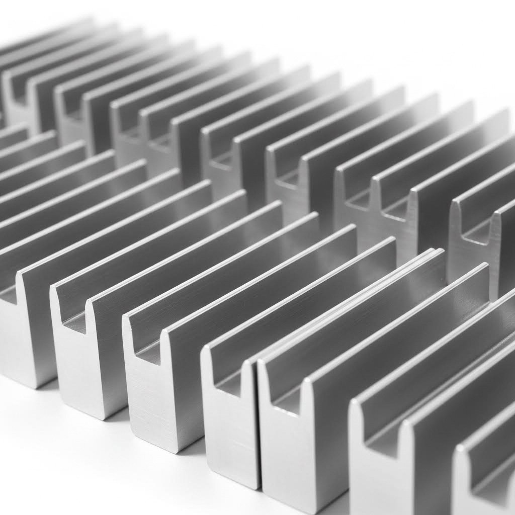
Here's where theory meets manufacturing reality. You can design the most thermally optimized finned heat sink on paper, but if it can't be extruded, you're back to square one. Understanding the relationship between fin geometry and extrusion constraints separates engineers who specify successfully from those who face costly redesigns. Let's explore the critical parameters that govern aluminum heat sink fins—and why these limitations exist.
Why do heat sink fins matter so much? It comes down to a simple principle: heat transfer occurs at surfaces. The more surface area you expose to airflow, the more heat you can dissipate. But here's the catch—cramming more fins into a given space doesn't automatically improve cooling.
Fin spacing directly affects how air moves through the finned heatsink. Space fins too tightly, and airflow becomes restricted. Space them too widely, and you sacrifice valuable surface area. Finding the sweet spot depends entirely on your cooling method:
As extrusion specialists note, one project reduced fin spacing from 2.5mm to 1.2mm expecting better results—instead, the unit ran hotter because trapped air couldn't escape efficiently. More fins doesn't always mean better cooling.
The physics of forcing aluminum through a die creates inherent constraints that every extrusion heat sink design must respect. Understanding these limits prevents frustrating back-and-forth with manufacturers and ensures your thermal solution is actually manufacturable.
Fin Height-to-Gap Ratio (Aspect Ratio)
This is perhaps the most critical constraint for finned heat sink design. Standard aluminum extrusion typically limits the fin height-to-gap ratio to approximately 6:1 to 10:1. What does this mean practically? If your fin spacing is 3mm, your maximum fin height is roughly 18-30mm using conventional extrusion.
Why does this limit exist? During extrusion, aluminum must flow through narrow die openings to form fins. Extremely tall, closely-spaced fins require aluminum to flow through long, thin channels—a path that creates excessive friction and risks incomplete die filling or fin tearing.
Minimum Wall and Fin Thickness
The minimum fin thickness for extruded aluminum typically falls around 0.8mm to 1.5mm. Going thinner requires specialized processes like skiving or bonded fin construction—both significantly more expensive than standard extrusion.
Why can't fins be paper-thin? Aluminum must maintain enough structural integrity to flow through the die without buckling or tearing. Ultra-thin sections also lack the rigidity to withstand handling during manufacturing and assembly.
The Performance Trade-Off
These constraints create a fundamental tension in aluminum heat sink fins design. Higher fin density increases surface area, which improves theoretical cooling capacity. But denser fins also:
Research comparing different fin geometries reveals important insights. According to thermal studies, when the goal is maximizing heat transfer per unit of pressure drop, straight fins often outperform more exotic geometries. However, when heat transfer per unit volume is the priority, pin fins may offer advantages—though they're not achievable through standard extrusion.
The practical takeaway? Work within extrusion constraints rather than fighting them. A well-optimized design respecting 6:1 to 8:1 aspect ratios, appropriate fin spacing for your airflow conditions, and adequate base thickness will outperform an "optimal" design that requires expensive manufacturing workarounds. When standard extrusion can't meet your thermal requirements, that's when alternative approaches like skived fins or bonded assemblies enter the conversation—topics worth exploring as you evaluate your specific application needs.
Should you select from existing heatsink profiles or invest in custom tooling? This decision impacts your project timeline, budget, and ultimately thermal performance. Unlike many resources that push custom solutions exclusively, understanding when standard extruded heatsinks make sense—and when they don't—helps you make smarter procurement decisions.
The good news? Manufacturers maintain extensive libraries of ready-to-order shapes. Industry catalogs offer 260+ open die designs covering most common thermal management scenarios. But knowing which path suits your application requires understanding both options clearly.
Standard heatsink profile options fall into several categories, each suited to specific applications:
Standard profiles offer compelling advantages for many projects. As aluminum extrusion specialists note, these ready-made solutions eliminate custom die costs, ensure quick availability, and provide proven performance data from existing applications.
Consider standard extruded heat sink profiles when:
Here's what many engineers overlook: some manufacturers stock thousands of standard molds and can fast-match profiles reaching 90% similarity to your requirements. This approach saves both money and time while delivering performance close to a fully custom solution.
Custom heatsink profiles become attractive when standard options compromise your design intent. But the economics require careful analysis beyond the initial die investment.
Custom die development typically costs between $500 and $5,000+ depending on profile complexity, size, and manufacturer location. This upfront investment makes sense only when per-unit savings at volume offset the tooling expense—or when no standard profile can meet your requirements.
Custom extrusions make sense when:
The minimum order quantity (MOQ) equation also differs significantly. Standard profiles from stocked inventory may ship with MOQs as low as 100kg, while custom extrusions typically require 1,000kg (1.1 US tons) minimum orders. For prototyping or low-volume production, this difference dramatically affects feasibility.
Lead time considerations further complicate the decision. Standard profiles ship within days to weeks. Custom dies require design validation, tooling fabrication, trial runs, and approval processes—often extending timelines by 6-12 weeks before production begins.
A practical decision framework:
The reality is that most thermal management projects can succeed with standard extruded heatsinks, especially when combined with targeted secondary machining. Reserve custom tooling investments for applications where thermal performance, integration constraints, or production economics clearly justify the upfront commitment. Understanding this balance positions you to specify effectively while managing both budget and timeline expectations.
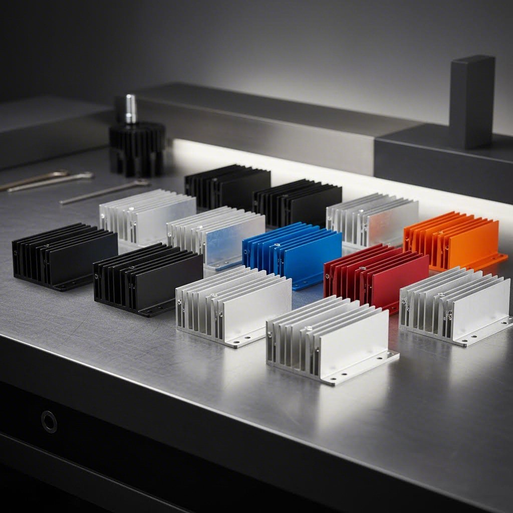
So you've got a freshly extruded aluminum profile emerging from the die. Now what? The journey from raw extrusion to functional metal heat sink involves critical secondary operations that determine whether your thermal solution actually performs as designed. These post-extrusion processes transform generic profiles into precision components ready for assembly—and understanding them helps you specify smarter.
Raw extrusions rarely meet final application requirements without additional processing. CNC machining and other secondary operations add the precision features that enable proper mounting, thermal contact, and system integration.
CNC Machining for Precision Features
Computer-controlled machining centers handle the most demanding modifications to extruded aluminum heat sink profiles:
As thermal management specialists note, CNC machining allows for high precision and accuracy, creating heatsinks with complex shapes and dimensions that standard extrusion alone cannot achieve.
Cutting and Drilling Operations
Beyond CNC work, aluminium heatsink extrusion profiles undergo several essential finishing steps:
These operations might seem routine, but their quality directly impacts thermal performance. A poorly machined mounting surface creates air gaps that increase thermal resistance—sometimes negating the benefits of expensive alloy selection or optimized fin geometry.
Here's something many engineers miss: surface treatments do more than improve appearance. The right finish can significantly boost heat dissipation, especially in passive cooling applications. Why? It comes down to emissivity—the ability to radiate heat.
Bare aluminum has surprisingly low emissivity, around 0.05. This means it reflects heat rather than radiating it efficiently. According to thermal studies, anodizing increases emissivity to approximately 0.85, allowing the heatsink extrusions to radiate up to 15 times more heat than untreated surfaces.
Anodizing Options
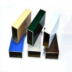
Anodizing creates a hard aluminum oxide layer through an electrochemical process. For extruded heatsink applications, Type II sulfuric acid anodizing offers the best balance of performance and cost. This treatment:
Black anodizing deserves special mention. Research indicates that black anodized heat sinks outperform lighter colors by 3-8% in natural convection applications due to higher emissivity. For forced-air cooling, color differences become negligible since convection dominates heat transfer.
Powder Coating and Specialized Treatments
When aesthetics or specific environmental protection matters, powder coating provides a durable, attractive finish. However, the thicker coating layer can reduce thermal performance compared to anodizing—something to weigh carefully in your specification.
Specialized treatments like micro-arc oxidation (MAO) create exceptionally hard, wear-resistant ceramic-like coatings. These excel in demanding environments but come at premium cost.
| Surface Treatment | Process Description | Thermal Impact | Durability | Typical Applications |
|---|---|---|---|---|
| Type II Anodizing | Electrochemical oxide layer (5-25 µm) | Excellent—increases emissivity to ~0.85 | High | Electronics, LED lighting, general thermal management |
| Type III Hard Anodizing | Thick oxide layer (25-150 µm) | Good—slightly thicker layer | Very High | Industrial equipment, harsh environments |
| Powder Coating | Electrostatic dry powder, heat-cured | Moderate—thicker layer can impede transfer | High | Outdoor enclosures, decorative applications |
| Micro-Arc Oxidation | Plasma-assisted ceramic coating | Good | Exceptional | Extreme wear/corrosion environments |
| Clear Chromate | Chemical conversion coating | Minimal impact | Moderate | Temporary protection, paint preparation |
Industry-Specific Considerations
Different applications demand tailored surface approaches. According to surface treatment specialists:
Streamlining Your Supply Chain
Working with a manufacturer offering comprehensive processing capabilities—from die development through surface finishing—eliminates coordination headaches between multiple vendors. When extrusion, CNC machining, and surface treatments happen under one roof, quality control improves and lead times shrink. This integrated approach proves especially valuable for complex extruded aluminum heat sink projects requiring tight tolerances and consistent finishes.
For thermal management applications demanding this level of integration, exploring custom aluminum extrusion services with end-to-end capabilities—including advanced surface treatments like anodizing in custom colors and micro-arc oxidation—can significantly streamline your project from prototype through volume production.
With secondary operations and surface treatments understood, the next critical decision involves matching your cooling approach to actual thermal loads. Understanding thermal resistance calculations helps you determine whether passive convection will suffice or whether forced-air or liquid cooling becomes necessary.
You've selected the right alloy, optimized your fin geometry, and specified surface treatments. But here's the question that separates functional designs from thermal failures: will your heat sink actually keep components within safe operating temperatures? Understanding thermal resistance calculations transforms guesswork into engineering confidence—and helps you choose between passive, forced-air, or liquid cooling before problems emerge.
Thermal resistance is the fundamental metric for heat sink selection. Think of it like electrical resistance, but for heat flow. The higher the thermal resistance, the harder it is for heat to escape from your component to the surrounding air.
According to Texas Instruments thermal design guidelines, the basic relationship is straightforward:
Junction Temperature (TJ) = Ambient Temperature (TA) + (Power Dissipation × Total Thermal Resistance)
Rearranging this equation reveals the maximum thermal resistance your heat sink can have:
θSA = (TJ(max) - TA) / PD - θJC - θCS
Where:
Here's a practical example. Imagine you're cooling a power device with TJ(max) of 125°C, θJC of 1.5°C/W, and 25W power dissipation. Your enclosure runs at 50°C ambient, and your thermal interface material adds 0.5°C/W. The calculation becomes:
θSA = (125 - 50) / 25 - 1.5 - 0.5 = 3.0 - 2.0 = 1.0°C/W maximum
This tells you exactly what thermal performance your heatsinks must achieve. Any heat sink with thermal resistance at or below 1.0°C/W under your airflow conditions will keep the component safe.
Once you know your required thermal resistance, the next decision involves cooling method. As thermal management experts explain, heatsinks function either passively through natural convection or actively using mechanisms like fans or liquid cooling to improve heat dissipation.
Natural Convection (Passive Cooling)
Passive cooling relies on buoyancy-driven airflow—hot air rises, drawing cooler air across fin surfaces. This approach works well for lower power applications where simplicity and reliability matter most. No fans mean no noise, no moving parts to fail, and no additional power consumption.
However, natural convection delivers significantly higher thermal resistance than forced methods. A heat sink rated at 1.0°C/W with 200 LFM airflow might jump to 3-4°C/W in still air. As technical documentation notes, volumetric thermal resistance ranges from 500-800 cm³·°C/W for natural convection compared to just 50-80 cm³·°C/W at 1000 LFM forced airflow.
Forced Air Cooling
Adding fans dramatically improves thermal performance. Forced convection pushes air through fin channels at controlled velocities, reducing the boundary layer that insulates fin surfaces. This approach enables tighter fin spacing, smaller heat sinks, or cooling of higher power loads.
The trade-off? Fans add cost, complexity, noise, and potential failure points. For large heat sinks in industrial settings, fan reliability becomes a maintenance consideration.
Liquid Cooling
When air cooling reaches its limits—typically above 500-1000W or in compact, sealed enclosures—liquid cooling enters the picture. Water or specialized coolants carry heat away far more efficiently than air, enabling thermal resistance values impossible with convection alone.
Liquid-cooled assemblies require pumps, tubing, cold plates, and often radiators. The complexity and cost increase substantially, but so does cooling capability.
Matching Cooling Approach to Application
Different applications typically favor specific cooling strategies based on power levels, environmental constraints, and reliability requirements:
Making the Right Choice
Start with passive cooling and move toward active solutions only when calculations demand it. A well-designed passive system costs less, lasts longer, and requires zero maintenance. If your thermal resistance requirements fall within 2-5°C/W and your enclosure allows adequate airflow, natural convection deserves serious consideration.
When passive cooling falls short, forced air typically offers the best balance of performance, cost, and complexity for most applications. Reserve liquid cooling for situations where thermal loads genuinely exceed air cooling capabilities or where acoustic constraints prohibit high-velocity fans.
Remember that thermal calculations represent worst-case scenarios. If your large heat sink operates within limits during maximum ambient temperature and full load conditions, it will perform even better under typical operating conditions. This margin provides reliability insurance without over-engineering your solution.
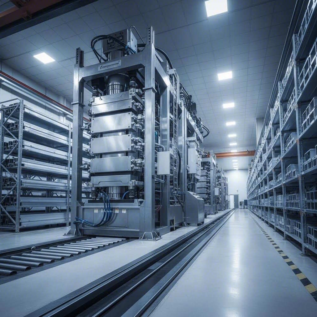
You've mastered alloy selection, fin geometry, and thermal calculations. Now comes the decision that determines whether your carefully engineered design becomes reality: choosing the right heat sink supplier. The wrong manufacturing partner can turn an optimized thermal solution into a costly headache—missed tolerances, inconsistent quality, or communication breakdowns that delay production for weeks.
Finding reliable aluminum heat sink suppliers requires evaluating far more than price quotes. A true manufacturing partner brings technical expertise, process capabilities, and supply chain reliability that impact your project from prototype through volume production. Let's examine the critical factors that separate capable heat sink manufacturers from those who will leave you troubleshooting quality issues.
Not all custom heat sink manufacturers deliver equal value. The difference often becomes apparent only after you've committed—which is why thorough upfront evaluation matters. Here's what to assess before signing any purchase orders.
Manufacturing Capabilities and Equipment
The extrusion press range tells you immediately what a heatsink manufacturer can actually produce. As discussed earlier, press tonnage determines profile complexity and size. A supplier with only small presses cannot produce the large, intricate aluminum heatsinks your high-power application might require.
Look for manufacturers with diverse press capabilities—ideally ranging from 600T for smaller profiles up to 5500T or higher for demanding extrusions. This range ensures flexibility as your product requirements evolve. According to aluminum extrusion specialists, facilities with multiple extrusion lines and automated systems typically outperform smaller operations in meeting delivery windows.
Secondary Processing Options
Raw extrusions rarely meet final application requirements. Your heat sink supplier should offer comprehensive secondary operations under one roof:
As industry analysis indicates, a reputable manufacturer will typically have access to advanced processes such as CNC machining, extrusion, die casting, and cold forging—allowing for high levels of customization and precision.
Surface Treatment Variety
Different applications demand different finishes. Your aluminum heat sinks manufacturer should offer:
In-house surface treatment eliminates coordination between multiple vendors and ensures consistent quality from extrusion through finishing.
Technical Support Depth
The best heat sink manufacturers function as engineering partners, not just order takers. Evaluate their technical support capabilities:
A supplier with strong technological expertise helps you avoid costly design iterations. As thermal industry experts note, innovative manufacturers invest in the latest technological advancements to ensure their products stay ahead in terms of efficiency and effectiveness.
Quality Certifications
Certifications provide objective verification of manufacturing standards. Look for:
These certifications indicate commitment to process control, traceability, and continuous improvement. For industries with stringent regulations, proper certification isn't optional—it's essential for supply chain qualification.
With evaluation criteria understood, how do you systematically assess potential suppliers? Use this prioritized checklist to compare aluminum heat sink suppliers objectively:
Initiating Your Project Successfully
Once you've identified promising suppliers, the project initiation process sets the tone for your partnership. Start by providing comprehensive specifications—detailed drawings, tolerance requirements, surface finish expectations, and projected volumes. The more information you share upfront, the more accurate your quotations and the fewer surprises during production.
Request physical samples before committing to volume orders. As supplier evaluation guides recommend, validate extrusion precision, surface finish, and material consistency before signing production contracts. For critical applications, consider factory audits—either in-person or virtual—to verify capabilities firsthand.
Factory-direct relationships offer distinct advantages over working through distributors or trading companies. Direct communication with engineering teams speeds problem resolution. Elimination of middlemen typically reduces costs. And direct accountability creates stronger motivation for quality and delivery performance.
For thermal management projects requiring this level of integrated support, exploring custom aluminum extrusion services with comprehensive capabilities—from 600T to 5500T press capacity, advanced CNC machining, and extensive surface treatment options including custom-color anodizing—provides the end-to-end partnership that transforms specifications into reliable production.
Building Long-Term Value
The right heat sink supplier relationship extends beyond individual orders. Look for partners who invest in your success through continuous improvement suggestions, proactive communication about potential issues, and flexibility when requirements change. A supplier focused on long-term partnership value—rather than maximizing short-term margins—becomes a genuine competitive advantage for your thermal management products.
Remember that the lowest quote rarely delivers the lowest total cost. Quality failures, delivery delays, and communication frustrations add hidden expenses that erode apparent savings. Invest time in thorough supplier evaluation now, and you'll avoid the costly lesson of learning these differences the hard way.
The heat sink extrusion process involves heating aluminum billets to approximately 400-500°C, then forcing the softened metal through precision steel dies using hydraulic pressure. The aluminum emerges with the exact fin profile engineered into the die. After extrusion, the profile undergoes controlled cooling, stretching for straightness, and cutting to length. Press tonnage ranges from 600T for simple profiles to 5500T+ for complex, large heat sinks with intricate geometries.
6063-T5 aluminum is the optimal choice for most heat sink applications, offering thermal conductivity of approximately 200 W/m·K and excellent extrudability for complex fin geometries. 6061-T6 provides higher mechanical strength (310 MPa tensile) but lower thermal conductivity (170 W/m·K), making it suitable when the heat sink must also serve structural functions or withstand significant vibration in automotive or aerospace applications.
Choose standard profiles when thermal requirements fall within common ranges, project timelines are tight, or volumes don't justify tooling costs. With 260+ standard shapes available, many projects achieve 80%+ design requirements without custom dies. Custom extrusions become worthwhile when specific fin geometries are essential, production exceeds 1,000-5,000 units to offset die costs ($500-$5,000+), or unique mounting features are required.
Yes, anodizing significantly enhances thermal performance in passive cooling applications. Bare aluminum has emissivity around 0.05, while anodizing increases it to approximately 0.85—enabling the heat sink to radiate up to 15 times more heat. Black anodized finishes outperform lighter colors by 3-8% in natural convection scenarios. For forced-air cooling, color differences become negligible since convection dominates heat transfer.
Standard aluminum extrusion limits fin height-to-gap ratios to approximately 6:1 to 10:1. For example, 3mm fin spacing allows maximum fin heights of 18-30mm. Minimum fin thickness typically ranges from 0.8mm to 1.5mm. Tighter spacing than 2mm can actually reduce cooling performance by restricting airflow. Symmetrical fin patterns are preferred since asymmetric designs cause uneven metal flow during extrusion.



 serviço on-line
 0086 136 3563 2360
 sales@sxalu.com
 +86 136 3563 2360
 português
 English
 français
 Deutsch
 русский
 español
 العربية
 ไทย
ไทย Việt
Việt Українська