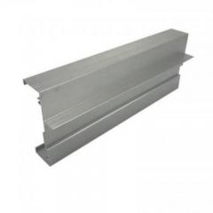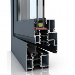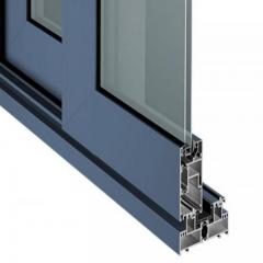
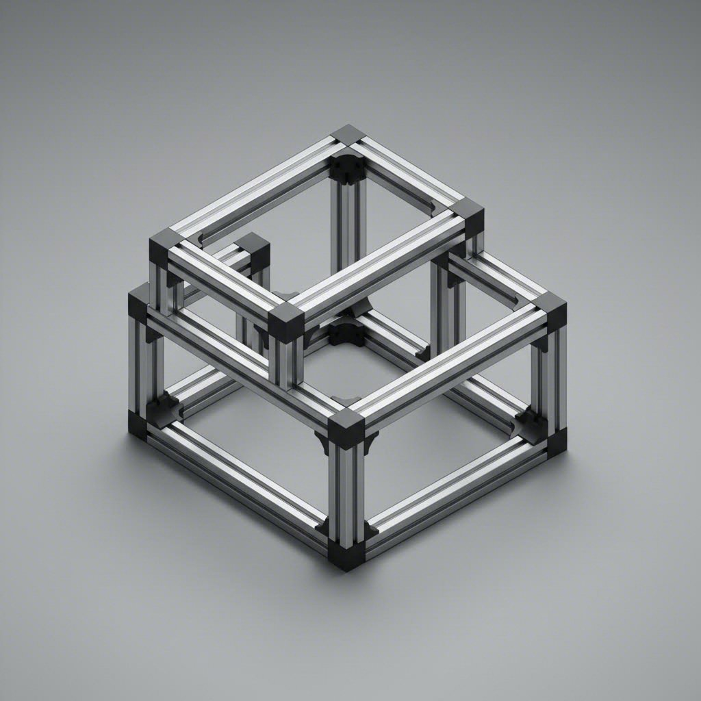
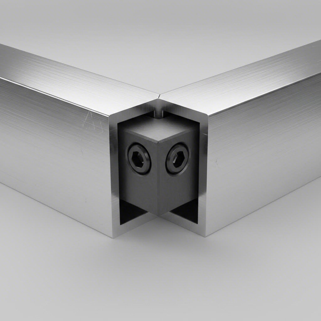
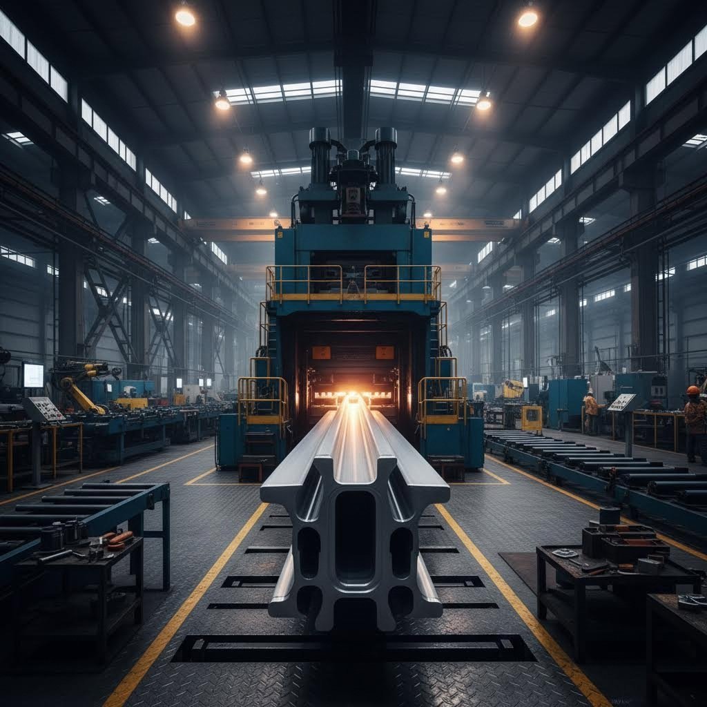
When you're designing structural frames or industrial equipment in SolidWorks, you'll quickly encounter a fundamental building block that shapes modern manufacturing: aluminum extrusion profiles. These are precisely engineered shapes created by forcing heated aluminum billets through specialized dies under high pressure, producing continuous cross-sections with remarkable dimensional consistency. The result? Lightweight yet incredibly strong structural components that form the backbone of everything from robotic workstations to safety enclosures.
But here's the thing—understanding how these profiles work in the physical world directly impacts how effectively you can model them digitally. For SolidWorks users, mastering aluminum extrusion profiles means bridging the gap between CAD design and real-world manufacturing, ensuring your digital models translate seamlessly into production-ready components.
Have you ever wondered why so many industrial applications rely on extruded aluminum rather than traditional welded steel? The answer lies in a powerful combination of modularity, strength-to-weight ratio, and design flexibility. Unlike welded structures that require extensive fabrication, aluminum extrusion profiles feature T-shaped slots running their entire length, enabling quick yet secure connections without drilling, welding, or permanent modifications.
According to industry experts at Vention, aluminum weighs approximately one-third of steel while delivering comparable strength performance. This characteristic makes extrusion profiles aluminum the preferred choice for applications where weight matters—mobile workstations, robotic arms, and reconfigurable production lines all benefit from this material advantage.
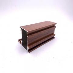
The natural formation of aluminum oxide on extruded surfaces provides built-in corrosion resistance, extending the lifespan of structures even in demanding industrial environments. This self-protecting quality, combined with the material's recyclability, positions aluminum extrusions as both a practical and sustainable engineering solution.
For SolidWorks designers, industrial aluminum extrusion profiles represent more than just catalog parts—they're the foundation for efficient structural design workflows. When you understand the relationship between physical manufacturing processes and digital modeling requirements, you can create designs that are not only visually accurate but also manufacturing-ready.
Consider this: every aluminum extrusion profile you model in SolidWorks corresponds to an actual die that exists at a manufacturing facility. The cross-sectional geometry you sketch must match real-world specifications, or your frame won't assemble correctly when fabricated. This connection between digital design and physical production is precisely why SolidWorks includes specialized tools for working with these profiles.
The applications where these profiles prove essential span virtually every manufacturing sector:
Each of these applications demands precise modeling in SolidWorks, where the aluminum extrusion profile serves as both the structural element and the design constraint. By understanding the available profile types—from compact 20x20mm sections for light-duty applications to heavy-duty options designed for next-generation collaborative robots—you'll make informed decisions that balance performance, cost, and manufacturability from the very first sketch.
Now that you understand what aluminum extrusion profiles are and where they're used, the next question becomes: what's the best way to model them in SolidWorks? While you could technically create frame structures using traditional part modeling or bottom-up assemblies, there's a purpose-built toolset that transforms how designers approach aluminum profile extrusion frame projects—the Weldments feature.
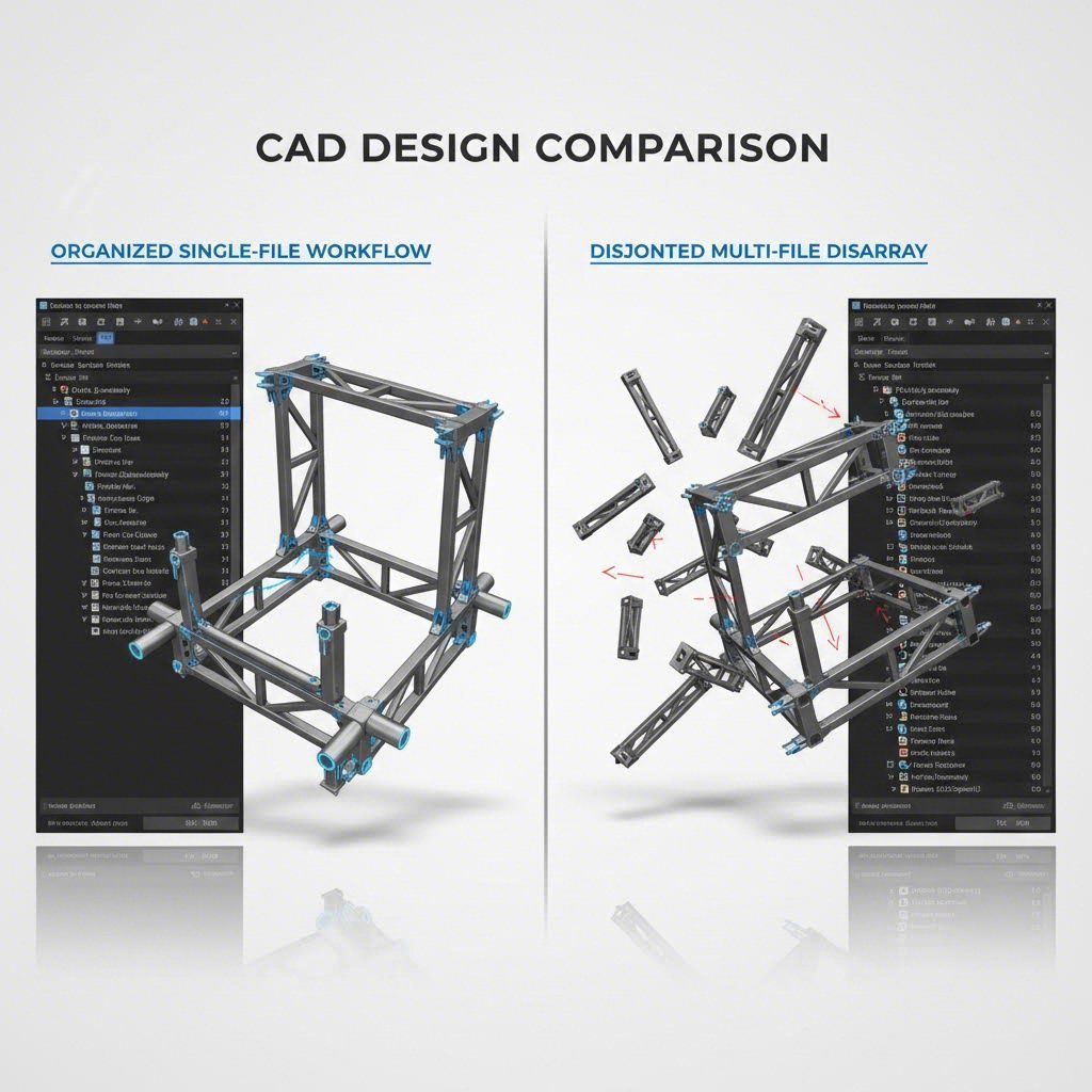
Think of Weldments as SolidWorks' answer to a simple but powerful question: how do you efficiently design structures made from linear profiles without creating dozens of individual part files? The answer involves treating your entire frame as a single multi-body part, with specialized tools that handle everything from profile placement to automatic cut list generation.
Here's what makes Weldments genuinely different from other modeling approaches. According to GoEngineer's technical guide, the Weldments tool allows you to create 3D structures using components with multiple profiles and various end-conditions—all within a single multi-body part file. This means your entire t-slot aluminum profiles extrusion frame exists as one manageable file rather than an assembly containing hundreds of separate components.
The workflow begins with a wireframe sketch—either a 3D sketch or multiple 2D sketches on different planes. This wireframe defines the centerlines where your structural members will be placed. Once your sketch geometry is complete, you simply apply the Structural Member command, select your desired profile from the library, and SolidWorks automatically generates the extruded shapes along your sketch paths.
What happens at the corners? This is where Weldments really shines. The system automatically groups continuous selections of sketch segments and applies corner treatments based on your specifications. You can choose mitered joints where profiles meet at angles, coped ends where one profile wraps around another, or simple butt joints where members terminate at intersecting faces. These operations that would require extensive manual work in traditional modeling happen almost instantaneously with solidworks aluminum extrusion weldment profiles.
Sounds complex? It's actually remarkably straightforward once you understand the core advantage. As explained by CATI's technical comparison, the fundamental difference comes down to what information you can extract from your model. Traditional bottom-up assemblies give you a bill of materials with part quantities, but you have to hunt through individual part drawings to find cut lengths and fabrication details. Multi-body parts offer design flexibility with configurations, but still lack easy-to-read cut lists.
Weldments solve both problems simultaneously. You get the multi-body design approach with its inherent flexibility, plus a much-welcomed cut list that automatically calculates lengths, quantities, and cutting angles for every structural member. This cut list updates dynamically whenever you modify the design—no manual property entry required.
The Trim/Extend command deserves special mention here. When you need to add or modify members that intersect with existing profiles, this tool lets you select which bodies to trim and define the boundary conditions. You can use faces, planes, or other bodies as trimming references. According to Engineers Rule, this feature enables quick adjustments even late in the design process—something that would require significant rework in assembly-based approaches.
| Design Method | Advantages | Limitations | Best Use Case |
|---|---|---|---|
| Weldments Method | Automatic cut lists with lengths and angles; automatic corner treatments; single file management; trim/extend operations; reusable profile libraries | Initial setup time for custom profiles; less intuitive for non-linear structures | Aluminum profiles extrusion frame designs; fabricated steel structures; any project requiring cut lists |
| Bottom-Up Assembly | Clear part-level BOMs with quantities; familiar workflow; individual part drawings available | No automatic cut list; must manually track cut lengths; many separate files to manage; tedious corner treatments | Projects with purchased components; designs requiring individual part documentation |
| Imported Parts Method | Quick access to manufacturer models; accurate geometry from suppliers; no profile creation needed | Limited parametric control; file format compatibility issues; potential dimensional inaccuracies; no integrated cut list functionality | Visualization and concept models; projects using specific manufacturer catalogs |
The productivity gains become even more apparent when changes are required. Imagine you've designed an aluminum profile extrusion frame and your client requests a different profile size. With Weldments, you simply edit the Structural Member feature and select a new profile—the entire structure updates, including all trim conditions and the cut list. In a traditional assembly, you'd face hours of rework replacing individual parts and re-establishing mates.
For teams working on machine frames, workbenches, safety enclosures, or any application involving structural profiles, investing time in learning the Weldments workflow pays dividends on every subsequent project. The combination of automatic documentation, flexible design modification, and single-file management makes this the definitive approach for professional aluminum extrusion frame design in SolidWorks.
With the Weldments workflow established, the next critical step is understanding which profiles to actually use. When you open the Structural Member library in SolidWorks, you'll encounter a seemingly endless array of profile options—each identified by cryptic numbers like 2020, 4040, or 4080. What do these designations mean, and how do you select the right one for your application?
Understanding standard aluminum extrusion profiles and their naming conventions isn't just helpful—it's essential for creating designs that work in the real world. The numbers you see represent actual dimensions, and knowing how to decode them will save you countless hours of confusion when specifying parts for fabrication.
Here's the good news: the naming system is more intuitive than it first appears. According to 80/20's official naming guide, profile names typically follow a pattern: [Series Number]-[Profile Size]x[Profile Size/Shape]-[Additional Features]. The series number indicates the product category, while the profile dimensions tell you the actual cross-sectional size.
For metric profiles—which dominate European and Asian markets—the numbers directly represent millimeters. A 2020 aluminum extrusion profile measures 20mm x 20mm in cross-section. Similarly, a 2040 aluminum extrusion profile measures 20mm wide by 40mm tall. The pattern continues: 4040 means 40mm x 40mm, 4080 means 40mm x 80mm, and so on.
What about profiles like aluminum extrusion profiles 20x100? The same logic applies—20mm width with a 100mm height, creating a taller, more beam-like section for applications requiring greater rigidity in one direction.
Imperial systems work slightly differently. In the 80/20 system popular in North America, the series number (10 Series, 15 Series, 25 Series) corresponds to the T-slot width in fractions of an inch, while subsequent numbers indicate the profile's overall dimensions or number of T-slot channels. This distinction matters when you're working with suppliers—always confirm whether you're dealing with metric or imperial specifications.
Many designers search for a standard aluminum extrusion profiles pdf from their preferred supplier to keep dimensional data at their fingertips. These catalogs typically include not just dimensions but also moment of inertia values, weight per meter, and recommended fastener specifications—all critical information for structural calculations in SolidWorks.
Knowing the nomenclature is one thing; selecting the appropriate profile for your application is another. The decision comes down to balancing structural requirements, weight constraints, and cost considerations.
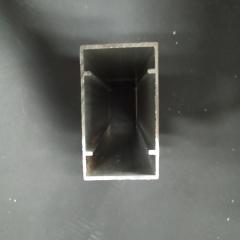
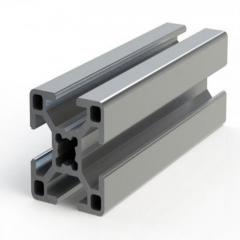
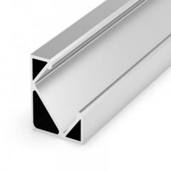
T slot aluminum extrusion profiles feature the classic T-shaped slots that accept standard hardware—T-nuts, brackets, hinges, and countless accessories. These slots run the full length of the profile, enabling connections at any point without machining. V-slot profiles, by contrast, feature a V-shaped groove designed specifically for linear motion applications. Wheels with V-shaped rims ride along these grooves, making V-slot ideal for CNC machines, 3D printers, and other motion systems.
The 2040 aluminum extrusion profile european standard has become particularly popular for applications requiring strength in one axis while minimizing weight. You'll find this profile extensively used in 3D printer frames where vertical rigidity matters more than lateral bulk.
| Profile Size | Dimensions (mm) | Typical Applications | Load Characteristics |
|---|---|---|---|
| 2020 | 20 x 20 | 3D printer frames, light enclosures, prototyping | Light duty; suitable for spans under 500mm with minimal loading |
| 2040 | 20 x 40 | CNC machines, linear motion systems, medium frames | Medium duty; increased rigidity in one axis; good for vertical supports |
| 3030 | 30 x 30 | Equipment stands, workbenches, display structures | Medium duty; balanced strength-to-weight ratio |
| 4040 | 40 x 40 | Machine bases, industrial workstations, safety guards | Heavy duty; suitable for most industrial frame applications |
| 4080 | 40 x 80 | Long-span beams, gantry systems, heavy equipment frames | Very heavy duty; high moment of inertia for extended spans |
| 4545 | 45 x 45 | Robotic cells, conveyor frameworks, precision structures | Heavy duty; often used in automated manufacturing systems |
| 8080 | 80 x 80 | Heavy machinery bases, structural columns, high-load applications | Extra heavy duty; maximum rigidity for demanding industrial use |
When you're unsure which profile to select, start by considering the longest unsupported span in your design and the maximum load it must carry. For light-duty applications with short spans—think desktop 3D printers or small enclosures—a 2020 profile often suffices. Move up to 4040 or larger for industrial machine frames, safety enclosures, or any structure where deflection could affect performance.
Remember that you can mix profile sizes within a single Weldments design. It's common practice to use heavier profiles like 4080 for main structural beams while employing lighter 2040 sections for secondary framing and cross-members. This approach optimizes both weight and cost while ensuring adequate strength where it matters most.
The choice between T-slot and V-slot ultimately depends on whether your design requires motion systems. For static frames, T-slot provides maximum flexibility for mounting accessories and making connections. For linear motion applications, V-slot eliminates the need for separate linear rails on certain axes—though for precision applications, dedicated linear guides typically outperform V-slot wheels.
With profile sizes decoded and selection criteria understood, the next question becomes practical: where do these profiles come from in your SolidWorks library, and what happens when the standard options don't match your requirements?
What happens when your project demands a profile that doesn't exist in the standard library? Maybe you're working with a specialized aluminum alloy extrusion profile from a regional supplier, or perhaps your application requires a proprietary cross-section designed specifically for your equipment. This is where understanding how to create custom aluminum extrusion profiles becomes invaluable.
The good news? SolidWorks makes custom profile creation surprisingly straightforward once you understand the underlying structure. Instead of being locked into pre-made options, you can build a personalized library of customized aluminum extrusion profiles that appear directly in your Structural Member dropdown—ready for use on any future project.
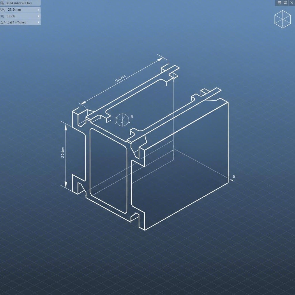
Before diving into the creation process, you need to understand what SolidWorks expects from a Weldment profile. The system isn't looking for a complex 3D model—it's looking for a simple 2D sketch that defines the cross-sectional shape of your extrusion.
Here's what makes a sketch Weldment-compatible:
For aluminum alloy extrusion profiles with internal channels or hollow sections, you'll need nested closed contours. The outer boundary defines the external shape, while inner boundaries create the hollow regions. SolidWorks automatically interprets these nested loops correctly when generating the structural member.
Ready to create your first custom profile? Follow these steps to build a profile that integrates seamlessly with the Weldments toolset:
C:\Program Files\SOLIDWORKS Corp\SOLIDWORKS\lang\english\weldment profiles. This is where the software looks for profile libraries.
Pro tip: If your custom profiles don't appear immediately, restart SolidWorks or use Tools > Options > System Options > File Locations to verify that the weldment profiles path is correctly configured.
The folder structure directly controls how profiles appear in the Structural Member interface. The top-level folder becomes the "Standard" selection, subfolders become "Type" options, and individual .sldlfp files become the available profile sizes. This hierarchy means you can organize hundreds of custom aluminum extrusion profiles in a logical, easily navigable structure.
For teams working on aluminum extrusion profile design projects, consider storing your custom profile library on a shared network drive. Update the File Locations setting on each workstation to point to this shared location, ensuring everyone accesses the same standardized profiles. This approach eliminates version conflicts and guarantees consistency across all team members' designs.
With your custom profiles created and organized, the question shifts from creation to acquisition: what if you need manufacturer-specific profiles that match commercially available products without building each one from scratch?
Creating custom profiles from scratch works well for proprietary designs, but what about when you need standard commercial profiles that match specific manufacturer catalogs? Building every profile manually would consume hours of design time—time better spent on actual engineering work. Fortunately, multiple sources offer ready-made aluminum extrusion profiles catalog files that integrate directly with SolidWorks Weldments.
The key is knowing where to look and understanding what you're getting. Not all pre-made profiles are created equal, and selecting the right source can mean the difference between smooth workflows and frustrating compatibility issues.
Your first stop should be the built-in SolidWorks Content library. According to GoEngineer's technical guide, complete profile packs are available for download directly through the Task Pane under Design Library > SOLIDWORKS Content > Weldments. Simply CTRL+click on any standard to download the complete pack, extract the .zip file to your weldment profiles folder, and you'll have dozens of profiles ready for immediate use.
Beyond the built-in options, major manufacturers provide CAD libraries for their specific product lines. Bosch aluminum extrusion profiles, for instance, are available through platforms like TraceParts, which hosts millions of CAD files from industrial suppliers worldwide. Similarly, item aluminum extrusion profiles and other major brands maintain downloadable libraries ensuring designers work with dimensionally accurate models matching their physical products.
Third-party CAD repositories like GrabCAD, 3D ContentCentral, and TraceParts aggregate profiles from multiple manufacturers into searchable databases. These platforms often provide native SolidWorks formats alongside universal file types, making integration straightforward for most projects requiring stock aluminum extrusions profiles.
Here's where things get interesting—not every downloaded profile will work seamlessly in your Weldments workflow. Before committing to a particular source for your aluminum extrusion profile catalog needs, consider these critical factors:
The trade-off between downloading pre-made models versus creating native profiles often comes down to control versus convenience. Downloaded profiles get you working immediately but may lack parametric flexibility or include unnecessary detail that bloats file sizes. Native profiles you create offer complete control over geometry and properties but require upfront investment in development time.
For most designers, a hybrid approach works best: use manufacturer-provided profiles for standard catalog items while reserving custom profile creation for specialized applications. This strategy ensures your aluminum extrusion profiles catalogue matches real-world products while maintaining flexibility for unique requirements.
With your profile libraries established—whether downloaded, custom-built, or a combination—the next challenge involves actually assembling these profiles into complete frame structures with proper corner treatments and hardware integration.
You've got your profiles selected, your Weldments workflow mastered, and your library organized. Now comes the real test of your t-slot aluminum extrusion profiles skills: making everything connect cleanly at the corners. This is where good frame designs become great ones—and where inexperienced designers often struggle.
Think about it: every aluminum frame extrusion profiles project involves dozens, sometimes hundreds, of intersections. How you handle these joints affects not just the appearance of your model but also the accuracy of your cut lists and the manufacturability of your final design. Let's dive into the advanced techniques that separate professional-grade Weldments work from amateur efforts.
When two structural members meet in SolidWorks, you have several options for how they intersect. The Trim/Extend command is your primary tool here, offering different corner treatment approaches depending on your structural and aesthetic requirements.
According to SolidWorks technical documentation, one of the most significant improvements in recent versions is the FULL FLUSH option for miter joints. Previously, creating mitered corners between differently sized profiles—say, a 60mm x 40mm rectangular tube meeting a 40mm x 40mm square tube—required manual calculations and multiple features. The system would calculate a bisecting angle that left one member too long and one too short.
The FULL FLUSH option automatically solves the correct angle for each structural member, performing both trim and extend operations with different angles on each profile. The result? A perfectly flush miter between two differently shaped structural members without the tedious manual matching that frustrated designers for years.
Here are the common corner treatment options and when to use each:
For complex intersections where multiple members converge—think of a corner where three profiles meet from different directions—you'll often need to apply trim operations sequentially. Start with the primary structural members, establish their corner treatment, then trim secondary members to the already-processed geometry. This layered approach prevents conflicts and gives you precise control over each joint.
A frame without hardware is just geometry—real aluminum extrusion corner profiles assemblies require T-nuts, brackets, gussets, and countless aluminum extrusion profile accessories to become functional structures. Integrating this hardware effectively requires understanding both the mechanical requirements and the SolidWorks workflow implications.
T-nuts form the backbone of T-slot frame connections. These specialized fasteners slide into the profile slots and provide threaded attachment points anywhere along the extrusion length. In your SolidWorks model, you have two approaches: represent T-nuts as simplified geometry within your Weldments part, or add them as separate components in an assembly that references your Weldment frame.
For most production documentation, the assembly approach works better. Create your complete Weldments frame as a single part file with all structural members and corner treatments defined. Then insert this part into an assembly where you add T-nuts, corner brackets, gussets, hinges, and other hardware as individual components. This separation keeps your Weldments cut list clean—showing only the aluminum profiles that need cutting—while your assembly BOM captures all the connection hardware.
Corner brackets and gussets deserve special attention for structural applications. These reinforcement elements significantly increase joint rigidity, particularly for frames subject to dynamic loading or vibration. When positioning gussets in your assembly, consider both the structural load paths and the practical installation sequence—a gusset that's perfectly positioned for strength but impossible to install without disassembling the frame isn't much use.
Interior brackets that connect perpendicular members typically require access from inside the frame cavity. Plan your assembly sequence so these connections can be made before closing the frame. For post-assembly adjustments, corner brackets with external access points allow tightening without frame disassembly—a critical consideration for equipment that may need field adjustment or reconfiguration.
The Trim/Extend command also helps when integrating hardware. If a bracket requires a specific clearance notch or a gusset needs a flat mounting surface, you can use the extend feature with custom end conditions to create these accommodations directly in your Weldments part. This approach maintains the single-file simplicity while ensuring your cut profiles arrive ready for hardware installation.
With corner treatments mastered and hardware integration planned, your frame design is nearly complete—but the real value of the Weldments approach emerges when you generate the documentation that takes your design from screen to shop floor.
Here's where the real payoff of working with SolidWorks aluminum extrusion profiles becomes crystal clear. You've designed your frame, applied corner treatments, and integrated hardware—but a beautiful 3D model doesn't cut aluminum. What your fabricator needs is precise documentation: cut lists with exact lengths, drawings showing assembly details, and files formatted for their specific workflow.
The Weldments approach you've been using wasn't just about faster modeling—it was building toward this moment. Every structural member you placed, every trim operation you applied, has been quietly generating the manufacturing data you need. Let's walk through extracting that information and preparing files that move your design from screen to production floor.
The transition from design to manufacturing documentation in SolidWorks follows a logical progression. Your Weldments part file contains all the geometry and cut information, but fabricators typically need that data presented in specific formats they can work with directly.
Start by examining your FeatureManager Design Tree. Below your structural member features, you'll find a Cut List folder that SolidWorks generates automatically. This folder organizes every body in your Weldments part by profile type and length, grouping identical members together. Expanding this folder reveals the foundation of your manufacturing documentation—each entry represents a distinct cut configuration your fabricator needs to produce.
Right-click the Cut List folder and select "Update" to ensure all bodies are properly categorized. SolidWorks sometimes requires this refresh after extensive editing, particularly when you've added or modified trim features. Once updated, each cut list item displays properties including length, quantity, and the profile description—the essential data for extrusion aluminum profiles fabrication.
For drawings, insert a Weldment Cut List table on your drawing sheet. This table pulls directly from your part's cut list folder, automatically populating with item numbers, descriptions, lengths, and quantities. You can customize which properties appear, add columns for material specifications or finish requirements, and format the output to match your shop's standard documentation.
The cut list is arguably the most valuable output of your entire Weldments workflow. Instead of manually measuring each member and compiling a spreadsheet—a process prone to errors and incredibly time-consuming for complex frames—SolidWorks extracts this information directly from the model geometry.
Here's what a typical aluminum extrusions profiles cut list looks like when properly configured:
| Item No. | Description | Length (mm) | Qty | Material |
|---|---|---|---|---|
| 1 | 4040 T-Slot Profile - Vertical Post | 1200.00 | 4 | 6063-T5 Aluminum |
| 2 | 4040 T-Slot Profile - Top Rail | 800.00 | 2 | 6063-T5 Aluminum |
| 3 | 4040 T-Slot Profile - Side Rail | 600.00 | 2 | 6063-T5 Aluminum |
| 4 | 2040 T-Slot Profile - Cross Brace | 756.50 | 4 | 6063-T5 Aluminum |
| 5 | 2020 T-Slot Profile - Panel Support | 380.00 | 6 | 6063-T5 Aluminum |
Notice how the cut list captures not just raw dimensions but also descriptive information that helps fabricators understand each piece's role. You control these descriptions through custom properties assigned to each cut list item—right-click any item in the Cut List folder and select "Properties" to add or modify this information.
The extrusion of aluminum profiles in your design may require additional fabrication details beyond simple length cuts. Mitered ends, drilled holes, or tapped threads all need documentation. SolidWorks handles this through relative views in your drawing—create detail views showing end conditions, add annotations for hole patterns, and dimension any secondary machining operations.
For sharing designs with external fabricators or an aluminum extrusion profiles factory, consider your export options carefully:
The aluminum profile extrusions in your cut list update automatically whenever you modify the design. Changed a frame dimension? The affected member lengths recalculate immediately. Swapped a 2040 profile for a 4040? The description updates throughout your documentation. This dynamic linking between model and documentation eliminates the version control headaches that plague manual documentation approaches.
When preparing files for production, always verify your cut list totals against a manual count of bodies in your model. Complex frames with many trim operations occasionally miscategorize members, particularly when bodies are split or combined during editing. A quick verification catches these discrepancies before they become expensive fabrication errors.
With production documentation complete, one critical decision remains: who actually manufactures these aluminum profile extrusions, and how do their capabilities influence what you can design?
Your SolidWorks model is complete, your cut list is generated, and your documentation package is ready for production. But here's a question that often gets overlooked until late in the project: who's actually going to manufacture these profiles? The choice of aluminum extrusion profile supplier directly impacts what you can design, how your finished product performs, and whether your specifications translate accurately from screen to reality.
Understanding manufacturing capabilities before you finalize designs saves revision cycles and prevents costly surprises. The best designers don't just know CAD—they understand the production processes that bring their models to life.
Ever wondered why certain profile geometries work perfectly while others fail during production? The answer lies in understanding the physical constraints of the extrusion process itself. When selecting aluminum extrusion profile manufacturers for your project, you're not just choosing a vendor—you're choosing a set of capabilities that either enable or limit your design freedom.
Alloy selection represents your first critical decision. The two most common options you'll encounter are 6063 and 6061 aluminum:
The extrusion press capacity at your chosen facility determines what profile sizes and shapes are achievable. Presses range from small 600-ton machines suitable for lightweight profiles up to massive 5500-ton systems capable of producing large aluminum extrusion profiles with complex geometries. If your design includes heavy structural sections or unusually wide profiles, verify that your aluminum profile extrusion manufacturers have appropriate press capacity before finalizing specifications.
Tolerances deserve careful attention in your supplier evaluation. Standard commercial tolerances work fine for general framing applications, but precision equipment or assemblies with tight fitment requirements may need tighter specifications. Discuss tolerance capabilities early—achieving precision adds cost, and not every aluminum extrusion profiles supplier can deliver the same dimensional accuracy.
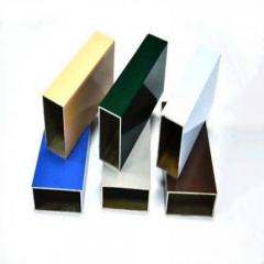
Surface treatment options significantly expand what's possible with your extruded profiles. Raw aluminum develops a natural oxide layer that provides basic corrosion protection, but most applications benefit from enhanced surface treatments:
Secondary processing capabilities often determine whether a supplier can deliver complete, ready-to-assemble components or just raw cut lengths. When evaluating industrial aluminum extrusion profiles suppliers, consider what additional operations they can perform:
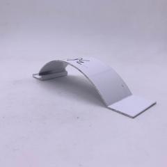
For example, Shengxin Aluminium demonstrates what comprehensive manufacturing capabilities look like in practice. With over 30 years of experience, their facility houses 35 extrusion presses ranging from 600T to 5500T—covering everything from delicate architectural profiles to heavy industrial sections. Their deep processing services include CNC machining centers for precise cutting, drilling, and bending, plus the full spectrum of surface treatments including anodizing in custom colors, powder coating, PVDF, and micro-arc oxidation.
This kind of vertically integrated aluminum extrusion profile manufacturer capability matters because it simplifies your supply chain. Instead of coordinating between an extruder, a machining shop, and a finishing house, a single-source supplier handles everything from die development through final surface treatment. For designers, this translates to fewer coordination headaches and more consistent quality across production runs.
When requesting quotes from aluminum profile extrusion suppliers, provide complete specifications including:
The relationship between your SolidWorks design and manufacturing reality becomes seamless when you understand these production considerations upfront. Designing with manufacturing capabilities in mind—rather than discovering limitations after submitting drawings—keeps projects on schedule and within budget while ensuring your aluminum extrusion profiles perform exactly as intended in the final application.
You've now journeyed through the complete workflow—from understanding aluminum profiles extrusion fundamentals to generating production-ready cut lists and selecting capable suppliers. But knowing the tools is only half the equation. What separates efficient designers from those constantly fighting their models comes down to discipline, organization, and awareness of common pitfalls.
Whether you're designing compact equipment enclosures or large aluminum extrusion profiles for industrial gantry systems, these best practices will streamline your workflow and prevent the frustrating rework that plagues poorly planned projects.
After working through dozens of structural aluminum extrusion profiles projects, patterns emerge. The designers who complete frames quickly and accurately follow consistent habits that compound into significant time savings. Here are the practices worth adopting:
Even experienced designers fall into predictable traps when working with aluminum extrusion profiles products. Awareness of these pitfalls helps you sidestep problems before they derail your project:
Remember: the goal isn't just creating geometry—it's producing documentation that translates seamlessly into manufactured components that assemble correctly the first time.
The intersection of CAD expertise and manufacturing knowledge defines truly effective profile aluminum extrusion designers. Architectural aluminum extrusion profiles for building facades and compact frames for laboratory equipment share the same fundamental workflow—but applying that workflow skillfully requires understanding both the software tools and the physical processes they represent.
As you build expertise in this specialized area, seek opportunities to visit fabrication facilities, discuss designs with experienced machinists, and examine assembled frames to understand how your digital decisions manifest in physical reality. This hands-on perspective, combined with the SolidWorks techniques covered throughout this guide, positions you to tackle aluminum extrusion frame projects with confidence—delivering designs that move efficiently from sketch to cut list to finished structure.
You can obtain aluminum extrusion profiles through multiple sources. First, access the built-in SolidWorks Content library via Task Pane > Design Library > SOLIDWORKS Content > Weldments, where you can CTRL+click to download complete profile packs. Additionally, manufacturers like Bosch and Item provide free CAD libraries through platforms like TraceParts and GrabCAD. For custom requirements, specialized suppliers such as Shengxin Aluminium offer technical support from die development through production, ensuring your specific profile needs are met with precise specifications.
Weldments treats your entire frame as a single multi-body part file with specialized tools for structural design. Unlike traditional assemblies that create separate part files for each member, Weldments automatically generates cut lists with lengths and quantities, applies corner treatments instantly, and allows trim/extend operations on intersecting profiles. This approach eliminates managing hundreds of individual files while providing manufacturing-ready documentation that updates dynamically when you modify the design.
These numbers represent the profile's cross-sectional dimensions in millimeters. A 2020 profile measures 20mm x 20mm, a 4040 is 40mm x 40mm, and a 4080 is 40mm x 80mm. The first number indicates width while the second shows height. This naming convention applies to metric profiles common in European and Asian markets. Imperial systems like 80/20 use series numbers (10, 15, 25 Series) corresponding to T-slot widths in fractions of an inch.
Create a new part file and sketch your profile cross-section as a fully closed contour on a single plane. Position the sketch origin at your desired insertion point, typically the centroid. Navigate to your SolidWorks weldment profiles folder, create custom subfolders for organization, then save the file as a Library Feature Part (.sldlfp). Your custom profile will appear in the Structural Member dropdown under your custom folder name, ready for use in any Weldments project.
Common surface treatments include anodizing (clear or colored finishes with excellent corrosion resistance), powder coating (unlimited color options with durable finish), and PVDF coating (superior UV resistance for outdoor applications). Advanced options like micro-arc oxidation create extremely hard ceramic-like surfaces for wear-resistant applications. Comprehensive manufacturers like Shengxin Aluminium offer all these treatments along with custom colors including champagne and rose gold, providing complete surface finishing solutions from their integrated facility.


 serviço on-line
 0086 136 3563 2360
 sales@sxalu.com
 +86 136 3563 2360
 português
 English
 français
 Deutsch
 русский
 español
 العربية
 ไทย
ไทย Việt
Việt Українська