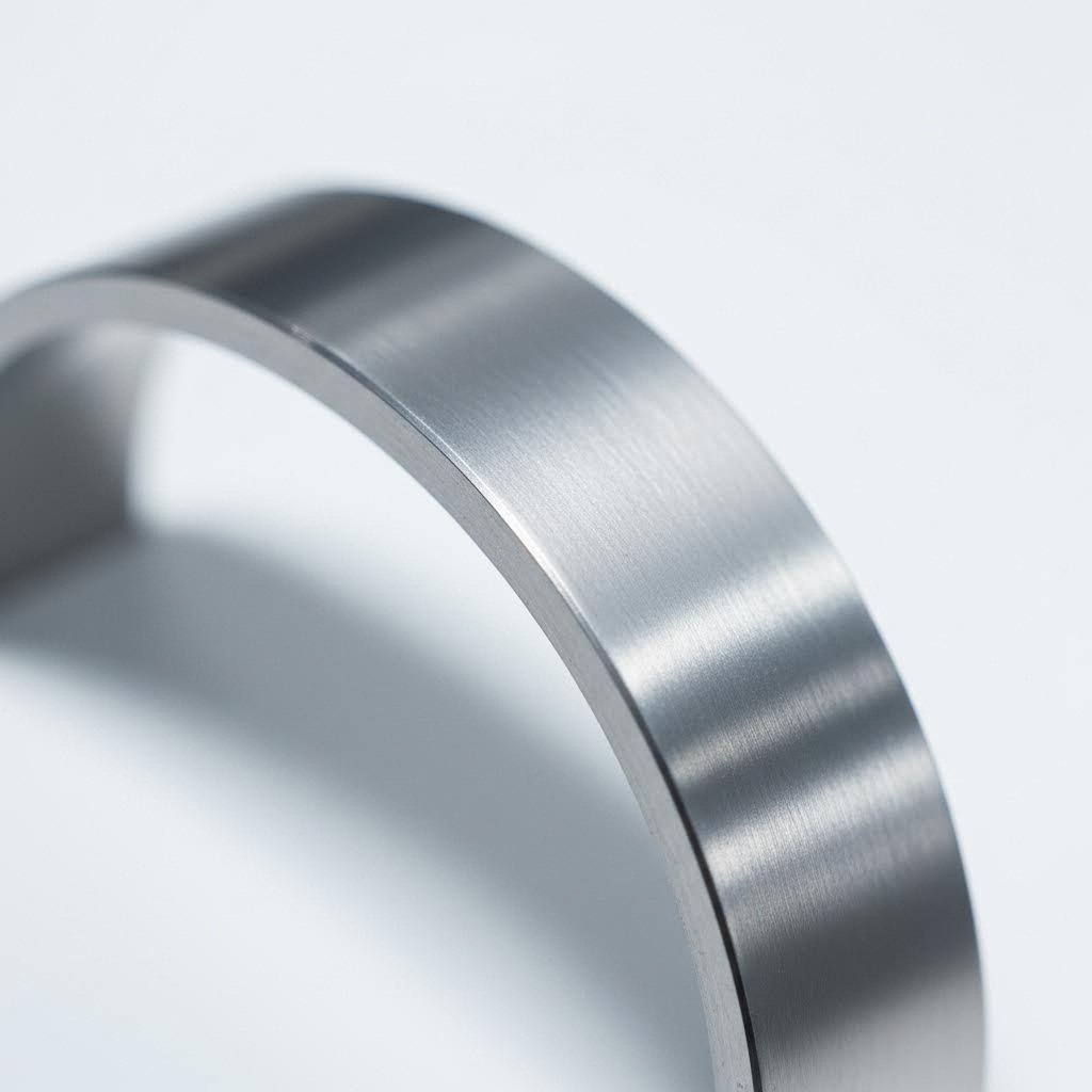
Imagine you're working with a complex aluminum profile—perhaps a hollow tube with varying wall thicknesses or an intricate architectural shape. Now you need to curve it precisely without cracking, wrinkling, or distorting its cross-section. This is where aluminum extrusion bending comes into play, and why choosing the right method matters more than you might think.
Aluminum extrusion bending is a specialized manufacturing process that shapes extruded aluminum profiles into curved configurations while preserving their structural integrity. Unlike working with simple flat sheets, curved aluminum extrusion projects involve components that have already been forced through a die to create specific cross-sectional shapes—hollow tubes, channels, angles, and custom architectural forms. The challenge lies in bending these pre-formed profiles without compromising their designed geometry.
When you select the wrong bending approach for your aluminum profile, the consequences extend far beyond a single failed part. You're looking at increased scrap rates, production delays, and potentially compromised structural performance in your final application. Each bending method applies force differently, and what works perfectly for a large-radius architectural curve may completely fail when applied to a tight-radius automotive component.
The stakes are particularly high because aluminum extrusion bending introduces multiple stresses into the material simultaneously—tension on the outer curve, compression on the inner surface, and torsional forces throughout. According to manufacturing research, common problems include surface defects like cracks or wrinkles, excessive springback leading to inaccurate bends, and twisting due to uneven stress distribution. Proper method selection addresses these challenges before they become costly mistakes.
Selecting the appropriate bending method based on your specific profile geometry, bend radius requirements, and production volume can reduce defect rates by preventing the mismatch between process capabilities and project demands—saving both material costs and production time.
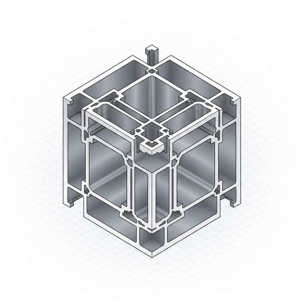
Here's what makes aluminum profile bending fundamentally different from sheet metal work: you're dealing with three-dimensional cross-sections that must maintain their shape throughout the bending process. A hollow rectangular tube behaves completely differently than a solid bar when curved. Internal cavities can collapse. Thin walls may wrinkle. Asymmetrical profiles tend to twist.
The aluminum flexibility you can achieve depends heavily on several geometric factors:
Throughout this guide, you'll discover a practical decision framework that matches your specific project requirements—profile type, bend radius, production volume, and precision needs—to the most effective bending method. Rather than piecing together fragmented information from multiple sources, you'll have a consolidated resource for making informed decisions that lead to successful outcomes the first time.
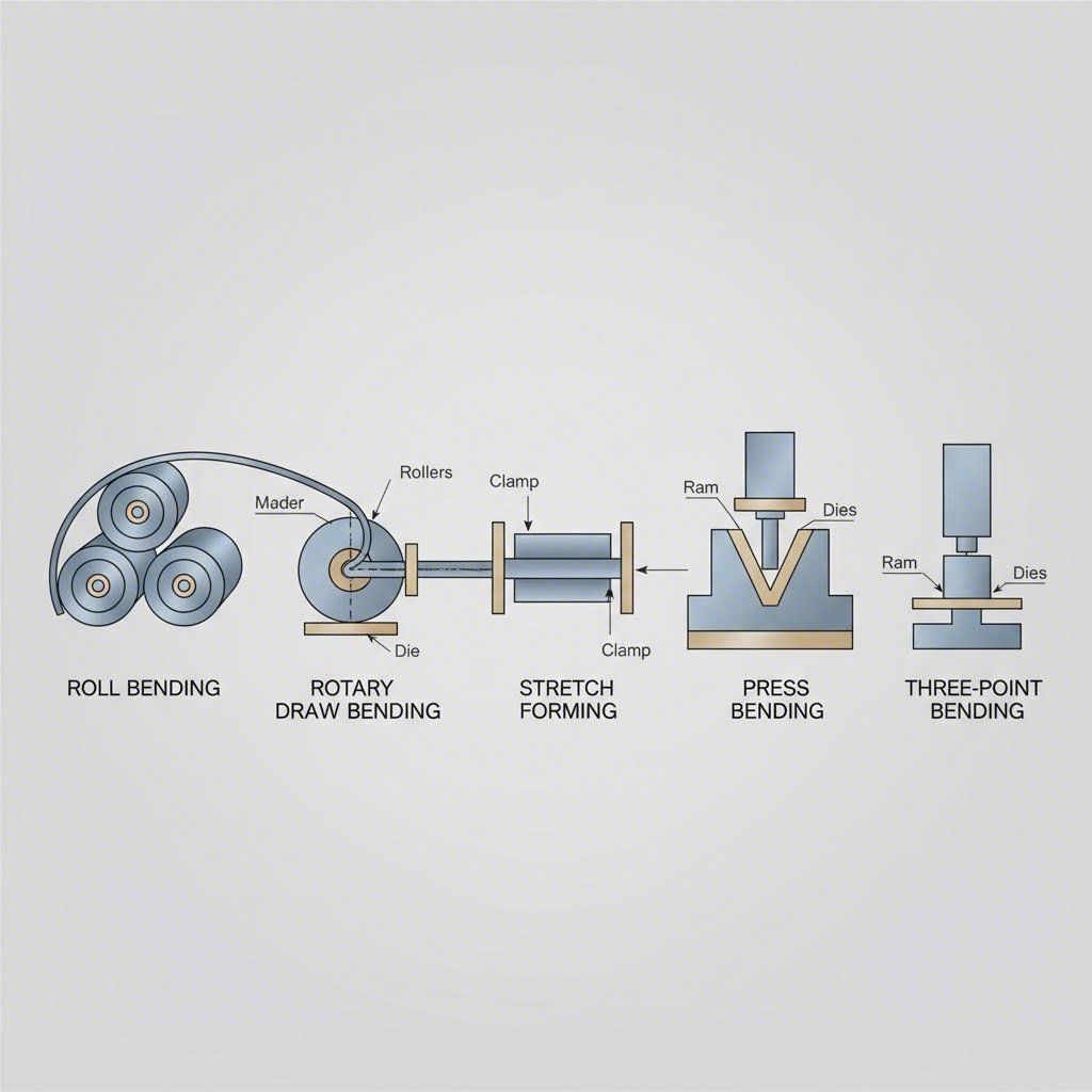
Now that you understand why profile geometry matters, let's explore the actual techniques used to shape bent aluminum into precise curves. Each method applies force differently, making some ideal for sweeping architectural arcs while others excel at tight-radius bends for transportation components. Knowing how these processes work helps you match your project requirements to the right aluminum forming approach.
Picture three rollers arranged in a triangle—two fixed at the bottom and one adjustable on top. As your aluminum profile feeds through, the top roller applies downward pressure, gradually curving the material over its entire length. This is roll bending, sometimes called three-roller bending, and it's the go-to method for creating wide, sweeping curves.
The mechanical principle is straightforward: continuous pressure applied incrementally produces gradual curvature without the need for expensive fixed-radius tooling. You can even create complete circles by passing the profile through multiple times. According to Wiley Metal, this method is often used for shaping large sections in architectural or construction applications like building facades and archways.
Best for: Long structural profiles, building frames, signage components, and any application requiring large-radius curves with minimal tooling investment.
When your project demands precise, tight-radius bends—think aircraft tubing or vehicle frame components—rotary draw bending delivers the control you need. The process clamps your aluminum profile against a circular die shaped to match its external contour, then rotates the die to wrap the material around it.
What makes this method special? Internal supports called mandrels can be inserted into hollow sections, preventing collapse during the bend. As noted in industry research from Inductaflex, rotary draw bending can achieve bend radii as tight as the section diameter itself—something no other method can match. Pressure dies provide additional support to maintain shape integrity throughout the process.
Best for: Complex profiles requiring tight bends, hollow sections needing internal support, and applications where repeatability and dimensional accuracy are critical.
Imagine clamping both ends of an aluminum extrusion, applying tension to elongate it slightly, then pressing it over a curved form die. This stretch forming process produces remarkably smooth bends with minimal springback—the tendency of metal to partially return to its original shape after bending.
The pre-tensioning step is the key advantage here. By stretching the material before forming, you achieve uniform curves with excellent surface quality and almost no post-bend correction needed. This makes stretch forming ideal for thin-walled panels and curved surfaces where finish quality matters, such as aircraft fuselage skins, marine hull components, and architectural metal cladding.
Best for: Large-radius bends on thin panels, applications requiring superior surface finish, and precision components where springback compensation is critical.
Two additional techniques round out your aluminium profile bending options. Press bending (also called ram or push bending) uses a semicircular ram pushed against the extrusion while pressure dies support it from both sides. The dies pivot as the profile wraps around the ram, allowing multiple bends to be placed close together. The minimum achievable radius is typically around four times the profile diameter.
Compression bending works similarly but clamps the extrusion against a stationary ram while a compression die wraps the material around it. This method achieves tighter radii—around three times the section diameter—and is often performed on twin-head machines to produce symmetrical bends at each end of a component.
When evaluating bending aluminum sheets or profiles, you'll want to compare methods across multiple parameters. This table consolidates the key differences to help you make informed decisions:
| Bending Method | Typical Bend Radius | Ideal Profile Types | Production Volume | Precision Level | Relative Cost |
|---|---|---|---|---|---|
| Roll Bending | Large radii (wide curves) | Long structural sections, architectural profiles | Low to high volume | Moderate | Low (minimal tooling) |
| Rotary Draw Bending | Tight (down to 1x diameter) | Hollow tubes, complex cross-sections | Medium to high volume | Very high | High (custom dies, mandrels) |
| Stretch Forming | Moderate to large | Thin panels, curved surfaces | Low to medium volume | Excellent | High (equipment and setup) |
| Press/Ram Bending | Medium (4x diameter minimum) | Solid and hollow sections | Medium volume | Good | Moderate |
| Compression Bending | Medium-tight (3x diameter) | Symmetrical components | Medium volume | Good | Moderate |
Notice how each method occupies a distinct niche. Roll bending offers the most economical path to large curves, while rotary draw bending commands higher tooling costs but delivers unmatched precision for tight-radius work. Stretch forming sits at the premium end, justified when surface quality and dimensional accuracy outweigh production efficiency concerns.
Understanding these five methods gives you a foundation for matching your project needs to the right process. But the aluminum alloy and temper condition you choose will significantly impact which methods—and which bend radii—are actually achievable for your specific application.
You've identified the right bending method for your project—but here's a critical question many engineers overlook: Is your aluminum alloy actually capable of achieving the bend you need? The truth is, alloy composition and temper condition often determine success or failure before your profile ever reaches the bending equipment. Choosing the wrong combination can lead to cracking, excessive springback, or complete material failure during forming.
Aluminum alloy extrusion comes in dozens of variations, each with distinct mechanical properties that directly affect bendability. Understanding these differences helps you specify materials that work with your chosen bending method rather than against it.
Temper designations describe the thermal and mechanical processing an aluminum alloy has undergone—and they dramatically influence how the material responds to bending forces. Think of temper as indicating how "hard" or "soft" the aluminum is. Softer tempers bend more easily, while harder tempers resist deformation but are more prone to cracking.
Here's what you need to know about common temper conditions:
When The Aluminum Association was asked about bending failures in 6061-T6 and 6063-T6 pipe, their response was clear: "For greater bendability, 6061-T4 or 6063-T4 pipes of the same size should be considered... After bending, the pipes can be strengthened by artificial aging." This approach—bending in a softer temper and then heat treating to restore strength—is standard practice for demanding applications.
Consider a real-world example: a project requiring 52 pieces of 8" x 4" x 1/4" rectangular 6061-T6 tubing bent to an 18-foot inside radius. When pressures were applied, the material failed almost immediately. The solution? Heat treating the tubing to reduce hardness before bending, after which all 52 pieces were successfully formed to specification.
Beyond temper, the alloy series itself determines baseline bendability. Aluminium alloy extrusion falls into numbered series based on primary alloying elements, and each behaves differently during forming:
Why does 6063 outperform 6061 for architectural applications? While both belong to the 6xxx series, 6063 contains less magnesium and silicon, resulting in slightly lower strength but significantly improved extrudability and formability. When your project involves decorative curves, window frames, or building facades, 6063 delivers smoother bends with less risk of surface defects.
Knowing when to specify material conditions upfront saves time and prevents costly failures. Consider requesting softer tempers from your supplier when:
For structural applications where T6 properties are ultimately required, the most reliable approach is ordering T4 temper, completing your bending operations, then artificially aging the parts to achieve T6 strength. This sequence maximizes your forming success rate while still delivering the mechanical properties your application demands.
With the right alloy and temper selected, your next consideration becomes equally important: designing profiles that inherently support successful bending through proper wall thickness ratios, cross-sectional geometry, and strategic placement of internal features.
You've selected your alloy, specified the right temper, and identified the ideal bending method. But here's what separates successful projects from costly failures: the profile design itself. Many bending problems are actually design problems in disguise—issues that could have been prevented during the engineering phase rather than discovered on the production floor.
Think about it this way: once you've committed to an extrusion die, your design is essentially locked in. Making changes after tooling is built means scrapping expensive dies and starting over. The smarter approach? Designing extruded aluminum parts with bending requirements in mind from the very beginning.
Wall thickness is perhaps the single most critical factor determining whether your aluminum extrusion systems will survive the bending process intact. Too thin, and the compressed inner surface buckles or collapses. Too thick, and the stretched outer surface may crack from excessive tensile stress.
So what are the actual numbers you should target? According to industry guidelines, the minimum bend radius relates directly to wall thickness:
For example, a hollow tube with 2mm wall thickness requires a minimum inside bend radius of 10-14mm to avoid collapse. Push tighter than this without internal support, and you're inviting failure.
But wall thickness alone doesn't tell the whole story. The ratio between wall thickness and overall profile dimensions matters too. A thin-walled hollow section with a large cross-section behaves very differently than a small-diameter tube with the same wall thickness. Larger profiles with thin walls are more susceptible to buckling because there's simply more unsupported material under compression.
Uniform wall thickness throughout your profile is equally important. When walls vary in thickness, stress concentrates at the transition points during bending. These stress concentrations become crack initiation sites. If your design absolutely requires varying thicknesses, incorporate gradual transitions rather than abrupt changes.
Beyond wall thickness, the overall geometry of your profile determines how it responds to bending forces. As Wiley Metal explains, the key to successful bending is controlling how each element of the extrusion moves—and this is far easier when the extrusion is symmetrical.
Symmetry matters more than you might expect. When a profile is symmetrical about the bend axis, forces distribute evenly across the cross-section. Asymmetric profiles experience uneven stress distribution, causing twisting and distortion that can render parts unusable. If your design must be asymmetric, expect to work closely with your bending specialist to develop custom tooling and process parameters.
The width-to-height ratio directly affects bending behavior. Profiles that are significantly wider than they are tall (in the direction of bending) tend to resist distortion better than tall, narrow sections. When bending an I-beam in the direction of its web, for instance, both flanges and the web itself must accommodate different radii—creating complex stress patterns that often result in buckling or cracking.
Internal ribs and webs can either help or hurt bendability depending on their placement. Ribs running parallel to the bend axis add stiffness where you need it, helping prevent collapse in hollow sections. However, ribs perpendicular to the bend axis can create stress concentrations and make forming more difficult. Strategic placement of internal features during the extrusion aluminium process can significantly improve your chances of success.
Corner radii within the profile deserve special attention. Sharp internal corners act as stress concentrators during bending. When the profile curves, these sharp corners experience amplified stress that can initiate cracks. Specify generous internal radii—typically a minimum of 0.5mm to 1mm for most applications—to distribute stress more evenly and improve formability.
Hollow profiles present unique challenges because there's nothing inside to resist the compressive forces on the bend's inner surface. Without support, thin walls simply buckle inward, distorting the cross-section and potentially creating kinks that weaken the structure.
This is where mandrels come into play. A mandrel is an internal support inserted into hollow sections during bending. It maintains the profile's internal shape by resisting the collapsing forces. Rotary draw bending with mandrel support is particularly effective for tight-radius bends on hollow tubing where maintaining cross-sectional integrity is critical.
When do you need mandrel support? Consider these factors:
Alternatively, you can design around the mandrel requirement by increasing wall thickness, adding internal stiffening ribs, or accepting a larger bend radius. As one source notes, filling the hollow interior with something that resists buckling is another option—though this complicates the process considerably.
Before finalizing any profile design intended for bending, verify these parameters in order of priority:
Addressing these design considerations during the engineering phase prevents the frustrating cycle of prototype failures, die modifications, and production delays. Remember: the extrusion die commits you to a specific geometry. Building bendability into that geometry from the start is far more economical than trying to force a poorly designed profile to cooperate.
With your profile optimized for forming success, the next step is matching these design parameters to the right bending method for your specific production requirements—volume, precision, and budget constraints all factor into this decision.
You've designed your profile with bendability in mind and selected the appropriate alloy and temper. Now comes the practical question: which bending method actually makes sense for your specific project? The answer depends on more than just technical capability—it requires weighing bend radius requirements, profile complexity, production volume, tolerance specifications, and budget constraints in the right order of priority.
Think of this decision as solving a puzzle where certain pieces must fit before others even matter. A method that can't achieve your required bend radius is immediately disqualified, regardless of how cost-effective it might be. Let's work through these decision criteria systematically so you can match your aluminium extrusion bending needs to the most appropriate process.
Production volume dramatically affects which bending approach delivers the best value. What works beautifully for 50 prototypes may become prohibitively expensive at 50,000 pieces—and vice versa. Understanding the relationship between volume, tooling investment, and per-piece costs helps you avoid both overspending on low-volume runs and underspending on high-volume production.
Low-volume production (1-100 pieces) favors methods with minimal tooling investment. Roll bending shines here because it uses adjustable rollers rather than fixed-radius dies. You can produce different curve radii without cutting new tools. Air bending on press brakes offers similar flexibility for simpler profiles. According to industry analysis, air bending is often the most cost-effective choice because it uses less force and simple tooling while allowing easy angle adjustments.
Medium-volume production (100-5,000 pieces) opens the door to methods requiring dedicated tooling. Rotary draw bending becomes economically viable because the tooling investment spreads across enough parts to justify custom dies and mandrels. Press bending and compression bending also fit this range well, offering good precision without the extreme tooling costs of high-precision methods.
High-volume production (5,000+ pieces) justifies significant upfront tooling investment because per-piece costs drop substantially. Stretch forming, despite expensive equipment and setup, delivers excellent consistency across large runs. Automated rotary draw bending with CNC control provides repeatability that manual methods simply cannot match. Research shows that high-volume runs can cut per-part cost by over half compared to small batches using the same technique.
The economics shift dramatically between these volume tiers. A custom rotary draw die costing $3,000-$10,000 makes no sense for 20 pieces but becomes negligible when amortized across 10,000 units. Conversely, paying premium per-piece rates for flexible low-volume methods becomes wasteful when your quantities justify tooling investment.
Sometimes tolerance specifications override all other considerations. If your application demands angular accuracy within ±0.5 degrees or positional tolerance under ±0.5mm, certain methods are simply non-starters regardless of cost or volume advantages.
Springback—the tendency of aluminum to partially return toward its original shape after bending—is the primary enemy of precision. Different methods handle this challenge with varying success:
According to tooling specialists, advanced CNC press brakes equipped with laser or contact-probe measurement systems can make real-time adjustments during forming, effectively countering batch-to-batch material variations. This closed-loop feedback represents the current state of the art in bending aluminum extrusions to precise specifications.
Consider your actual precision requirements carefully. Many projects specify tighter tolerances than the application truly requires—a habit that drives up costs unnecessarily. A structural frame that functions perfectly with ±1 degree tolerance shouldn't be specified at ±0.25 degrees simply because tighter sounds better.
How do you synthesize all these factors into a practical decision? The following matrix maps common project scenarios to recommended bending methods, helping you identify the best starting point for your specific situation:
| Project Scenario | Recommended Method | Why This Choice | Cost Consideration |
|---|---|---|---|
| Large-radius architectural curves, low volume | Roll Bending | Minimal tooling, adjustable radii, handles long sections | Low tooling cost, moderate per-piece |
| Tight-radius hollow tube bends, medium volume | Rotary Draw Bending with Mandrel | Prevents collapse, achieves tight radii, high repeatability | Moderate-high tooling, low per-piece at volume |
| Aerospace panels requiring smooth curves, any volume | Stretch Forming | Minimal springback, excellent surface quality, uniform results | High equipment cost, justified by quality requirements |
| Symmetrical bends at both ends of component | Compression Bending (Twin-Head) | Simultaneous forming, consistent results, efficient | Moderate tooling, efficient for specific applications |
| Multiple bend locations close together | Press/Ram Bending | Pivoting dies allow bends near each other | Moderate overall cost |
| Prototype development, varied specifications | Roll Bending or Air Bending | Flexibility to adjust without new tooling | Lowest upfront investment |
| High-volume production, tight tolerances | CNC Rotary Draw Bending | Automated repeatability, consistent quality control | High tooling investment, lowest per-piece cost |
Here's something many engineers overlook: a single project doesn't necessarily require a single bending method. Complex assemblies often benefit from combining techniques—using the optimal process for each specific bend rather than forcing one method to handle everything.
Imagine a railing system requiring both sweeping curves along its length and tight-radius returns at the ends. Roll bending handles the long curves efficiently, while rotary draw bending produces the tight returns with proper mandrel support. Attempting to accomplish both with only one method either compromises quality or dramatically increases costs.
Consider splitting your bending operations when:
The key is analyzing each bend independently, then determining whether combining methods reduces overall project cost compared to forcing a single-method approach. A slight increase in handling between operations often costs less than premium tooling or compromised quality.
Budget reality ultimately shapes every manufacturing decision. Understanding where costs accumulate in bending aluminium extrusion helps you allocate resources effectively:
Tooling investment represents the largest upfront cost difference between methods. Roll bending requires minimal dedicated tooling—often just adjustable roller positions. Rotary draw bending demands custom dies matching your exact profile geometry, plus mandrels for hollow sections. Stretch forming requires form dies shaped to your specific curve. These investments range from hundreds of dollars for simple roll bending setups to tens of thousands for complex rotary draw tooling.
Per-piece costs include machine time, operator labor, and material handling. Methods requiring multiple passes (like incremental roll bending) consume more time than single-operation processes. Complex setups with mandrel insertion add labor. However, these per-piece costs matter most at high volumes where even small savings multiply across thousands of units.
Scrap and rework rates factor into true cost calculations. A cheaper method that produces 15% scrap may actually cost more than a premium process with 2% rejection rates. According to manufacturing research, tooling selection alone significantly impacts defect rates—a poor choice drives up scrap rates, causes equipment damage, and ultimately determines whether a project is profitable.
When evaluating quotes from bending specialists, ensure you're comparing complete costs including tooling amortization, expected scrap rates, and any secondary operations required to achieve final specifications. The lowest per-piece price sometimes delivers the highest total cost.
With your bending method selected based on these decision criteria, the next challenge is ensuring that method produces defect-free parts consistently—which requires understanding how to prevent the three primary failure modes that plague aluminum bending operations.
You've selected the right bending method, designed your profile for success, and specified the appropriate alloy and temper. Now comes the challenge that separates good bending operations from great ones: preventing the defects that can turn perfectly planned projects into expensive scrap piles. Three primary failure modes plague curved aluminum extrusions—cracking, wrinkling, and springback—and each requires a distinct prevention strategy.
Understanding why these defects occur is the first step toward eliminating them. Material condition, tooling setup, and process parameters don't act independently—they interact in complex ways that either prevent or cause failures. Let's break down each defect type with actionable prevention steps you can implement immediately.
Cracking is perhaps the most serious bending defect because it's usually irreversible. When you see splits or fractures along the outer surface of a bend, the part is typically scrap. According to manufacturing research, cracks develop when the material cannot stretch enough during bending—the outer fibers experience tensile stress beyond the aluminum's elongation capacity.
Root causes of cracking include:
Warning signs to watch for: Before catastrophic cracking occurs, you may notice orange peel texture on the outer surface, hairline marks, or audible stress sounds during forming. These early indicators signal that you're approaching the material's limits.
Prevention techniques that work:
While cracking occurs on the stretched outer surface, wrinkling happens on the compressed inner surface of bends. You'll see wave-like patterns, folds, or buckles that compromise both appearance and structural integrity. Wrinkling is particularly problematic in curved aluminum extrusions destined for visible architectural applications.
Root causes of wrinkling include:
Warning signs to watch for: Minor surface waviness often precedes severe wrinkling. If you notice any unevenness developing on the inner curve during forming, stop and reassess your setup before continuing.
Prevention techniques that work:
Unlike cracking and wrinkling, springback isn't immediately visible as damage—but it's equally problematic. After you release the bending force, the aluminum partially returns toward its original shape. A bend set at 90 degrees might relax to 87 degrees. Over thousands of parts, this inconsistency creates assembly nightmares.
Springback occurs because aluminum stores elastic energy during bending. Once the tools release, that stored energy pushes the metal back. Aluminum has a relatively high ratio between elasticity and yield strength, meaning it can return farther than many other metals.
Factors affecting springback severity:
Compensation strategies ranked by effectiveness:
| Strategy | Effectiveness | Implementation Notes |
|---|---|---|
| Applying tension (stretch forming) | Very High | Pre-stretches material, leaving minimal elastic energy |
| Mandrel and die optimization | High | Proper tooling guides material precisely through the bend |
| Lowering bend speed | High | Allows material to flow and set more completely |
| Over-bending techniques | High | Intentionally bend past target angle, let springback pull to final position |
| Using larger radii | Moderate | Reduces elastic strain but may not suit all designs |
| Pre-heating material | Moderate | Varies by alloy and thickness; requires careful control |
CNC compensation makes precision achievable: Modern CNC machines can correct for springback automatically. These systems rely on real-time sensors that track radius changes, adaptive software that adjusts during the bend, and CAD/CAM files that include compensation instructions upfront. When paired with test cycles, automated adjustments remove most guesswork from the extrusion of aluminium alloys.
Test bending before production: Before bending high-value parts, run simulations or trial bends. Use FEA software to predict behavior, then record measurements from test parts to refine machine settings. This verification step prevents costly surprises during full production runs.
Preventing defects requires catching problems early—before they propagate through an entire production run. Establish these inspection checkpoints:
The interaction between material condition, tooling setup, and process parameters determines whether you produce quality curved aluminum extrusions or expensive scrap. Addressing all three factors systematically—rather than troubleshooting each defect in isolation—creates robust processes that deliver consistent results.
With defect prevention strategies in place, the next advancement in bending capability comes from modern CNC technology and integrated processing solutions that bring precision, repeatability, and efficiency to complex aluminum forming operations.
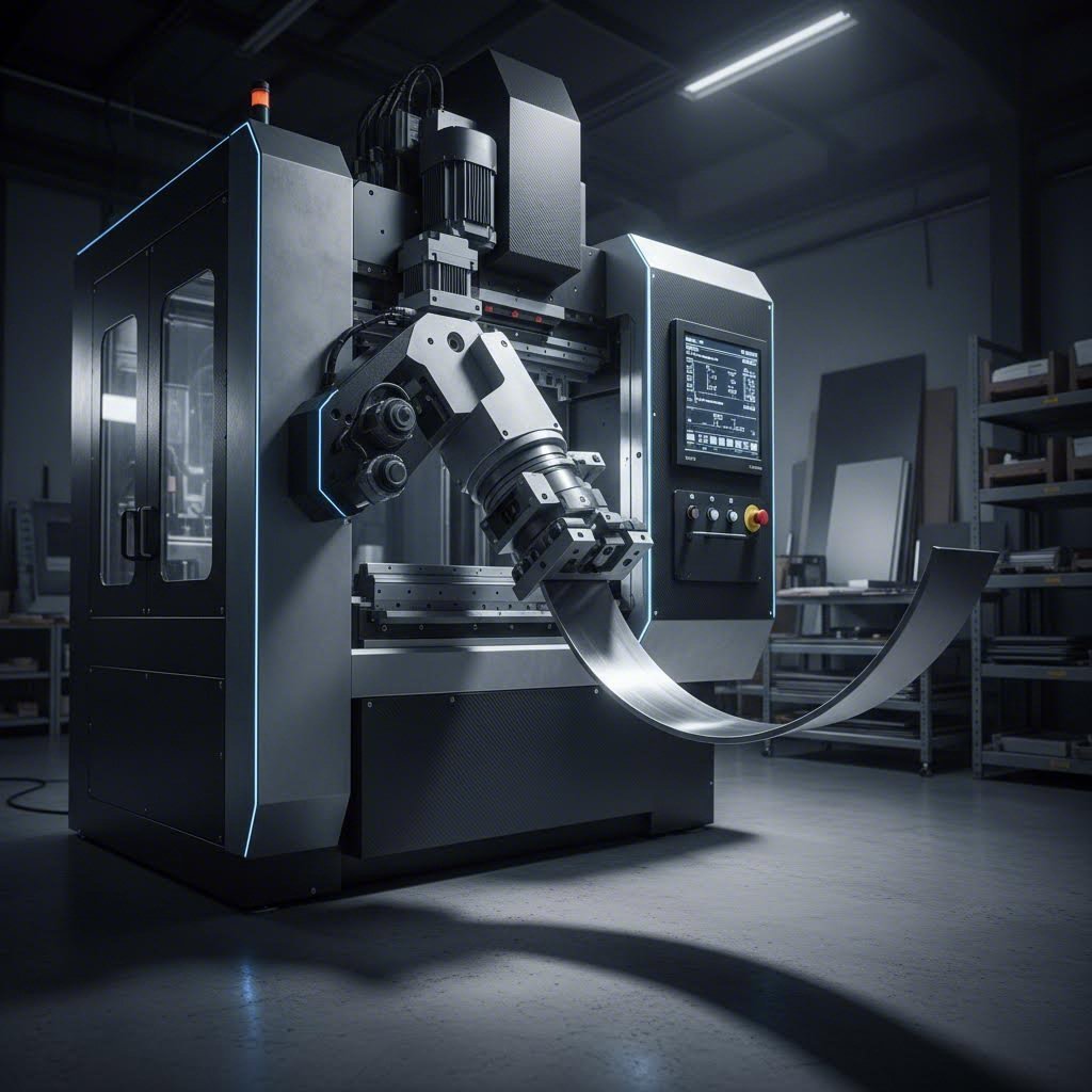
You've mastered defect prevention strategies—but here's where aluminum bending truly enters the modern era. While manual and semi-automated methods still dominate many shops, CNC aluminum bending technology has transformed what's possible in terms of precision, repeatability, and production efficiency. If you're producing more than a handful of parts, understanding these automated profile bending capabilities could fundamentally change your approach to curved aluminum projects.
The shift from traditional methods to computer-controlled bending isn't just about speed. According to industry analysis, CNC technology enables manufacturers to produce complex shapes and designs with minimal human intervention, significantly reducing the risk of errors while enhancing overall quality of the finished product.
Imagine programming your exact bend specifications once, then reproducing those precise curves across hundreds or thousands of parts without variation. That's the fundamental advantage of CNC-controlled bending systems—consistency that manual operations simply cannot match.
Modern CNC bending machines incorporate several technologies working together:
The springback challenge that plagues manual operations? CNC systems address it systematically. As one manufacturer explains, their operating system solves springback in just two steps: input the actual radius to get the coefficient, then input the compensation coefficient and start production. The workpiece can be reproduced at any time with identical results.
What does this mean practically? When scaling up production, thousands of parts of the same design maintain consistent dimensions from month to month. You get interchangeable parts from batch to batch—something that's extraordinarily difficult to achieve with manual methods regardless of operator skill.
Here's an efficiency opportunity many manufacturers overlook: why handle aluminum profiles multiple times when integrated processing can accomplish everything in a streamlined workflow? The most advanced facilities combine extrusion, cutting, drilling, machining, and bending under one roof—eliminating the logistics headaches and quality variations that plague multi-vendor supply chains.
Consider a typical project requiring curved aluminum components. The traditional approach involves:
Each handoff introduces potential for damage, dimensional inconsistencies, and communication errors. Integrated processing eliminates these risks while typically reducing lead times significantly.
Automated solutions now combine high-speed cutting with CNC machining centers that handle complex fabrication in single setups. These systems can take complex, manual die work and automate it—improving speed, safety, and quality simultaneously.
The benefits extend beyond logistics:
When evaluating facilities for complex curved aluminum projects, look for capabilities that span the complete production chain. The ideal partner offers die development expertise, extrusion capacity across multiple press sizes, and deep processing services including precision CNC bending.
For projects requiring this level of integration, manufacturers like Shengxin Aluminium provide end-to-end support with state-of-the-art CNC machining centers capable of precise cutting, drilling, and bending to exact specifications. With 35 advanced extrusion presses and comprehensive aluminum profile processing services, they offer technical support from die development through mass production—plus surface treatment options like anodizing and powder coating to complete your components.
The convergence of automation, CNC precision, and integrated processing represents the current state of the art in aluminium cold extrusion and forming. As industry observers note, the future promises even greater levels of efficiency through AI-driven optimization and IoT-enabled real-time monitoring—technologies already emerging in leading facilities.
With processing technology advancing rapidly, the final challenge becomes translating all these concepts into actionable steps for your specific projects.
You've absorbed a tremendous amount of information about aluminum bending best practices—from alloy selection and temper considerations to defect prevention and CNC automation. Now comes the moment that matters most: translating this knowledge into successful real-world projects. Whether you're planning your first curved extrusion or optimizing an established production line, having a structured approach ensures nothing critical gets overlooked.
Extrusion bending project planning doesn't need to be overwhelming. By following a systematic process and engaging the right partners early, you can avoid the costly trial-and-error cycles that plague poorly planned projects. Let's consolidate everything into actionable steps you can implement immediately.
Before committing to any bending approach, work through these prioritized actions in sequence. Each step builds on the previous one—skipping ahead often leads to expensive backtracking:
This sequence prioritizes the decisions that have the greatest impact on project success. A profile that cannot physically achieve your required bend radius—regardless of how well you've addressed everything else—will fail every time.
Here's a truth that experienced engineers learn quickly: early collaboration between designers and fabricators prevents more problems than any amount of troubleshooting after the fact. When you involve your bending partner during the design phase rather than after tooling is committed, you gain access to practical manufacturing insight that CAD software alone cannot provide.
What does effective collaboration look like?
For complex projects requiring precision bending combined with comprehensive surface treatment options like anodizing or powder coating, established manufacturers like Shengxin Aluminium offer end-to-end support with over 30 years of experience and factory-direct pricing. Their technical teams can guide you from die development through mass production, ensuring your curved aluminum components meet specifications without the coordination headaches of multi-vendor supply chains.
The most critical success factor in aluminum extrusion bending is addressing alloy selection, temper condition, profile geometry, and method matching as an integrated system—not as isolated decisions made by different teams at different times.
Successful bending projects share a common thread: they treat material properties, design parameters, and processing methods as interconnected variables rather than separate checkboxes. When these elements align, you achieve the goal this entire guide has been working toward—choosing right the first time and bending once, without costly iteration or wasted material.
The five primary methods are roll bending (ideal for large-radius architectural curves), rotary draw bending (best for tight-radius hollow tubes with mandrel support), stretch forming (excellent for aerospace panels requiring minimal springback), press/ram bending (suited for multiple bends close together), and compression bending (effective for symmetrical components). Each method applies force differently, making selection dependent on your bend radius, profile complexity, and production volume requirements.
For architectural bending, 6063 aluminum is preferred due to its superior formability and excellent surface finish. For applications requiring maximum bendability, 5052 aluminum bends easier than 6061 or 7075 with fewer cracks. The 3003 alloy offers very good formability and remains strong after bending. When higher strength is needed, consider ordering 6061 in T4 temper for easier bending, then artificially aging to T6 after forming.
Prevent cracking by ensuring your bend radius meets minimum requirements (5-7x wall thickness for hollow sections, 3-5x for solid), using softer temper conditions like T4 instead of T6, slowing bending speed to allow material flow, applying proper lubrication, orienting bends perpendicular to the grain direction, and inspecting material for surface defects before forming. For challenging bends, consider annealing the aluminum to soften it before the bending operation.
Springback is the tendency of aluminum to partially return toward its original shape after bending forces are released. Minimize it by applying tension during forming (stretch forming method), using mandrels and optimized dies, reducing bending speed, over-bending past the target angle to compensate, or pre-heating the material. Modern CNC bending machines can automatically compensate for springback using real-time sensors and adaptive software for consistent results.
Use mandrel support when bending hollow sections with wall thickness less than 10% of the outside diameter, when bend radii are tighter than 3 times the tube diameter, when cross-sectional deformation (ovalization) is unacceptable, or when working with thin-walled decorative profiles requiring precision fit. Rotary draw bending with mandrel support is particularly effective for tight-radius bends where maintaining the internal shape is critical to your application.


 serviço on-line
 0086 136 3563 2360
 sales@sxalu.com
 +86 136 3563 2360
 português
 English
 français
 Deutsch
 русский
 español
 العربية
 ไทย
ไทย Việt
Việt Українська