Ever watched a Play-Doh press squeeze dough through a shaped opening? That's essentially the aluminum extrusion definition in its simplest form. Of course, the industrial version involves significantly more heat, pressure, and precision—but the core concept remains identical.
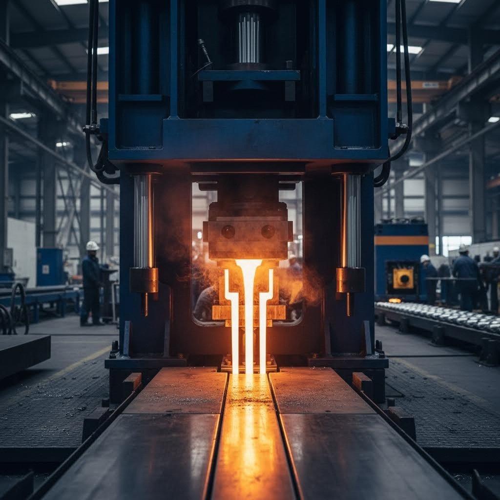
So, what is aluminum extrusions in technical terms? It's a manufacturing process where heated aluminum alloy billets are forced through a steel die with a specific cross-sectional profile. The result? Long, uniform shapes that can be solid, hollow, or semi-hollow—each tailored to exact specifications.
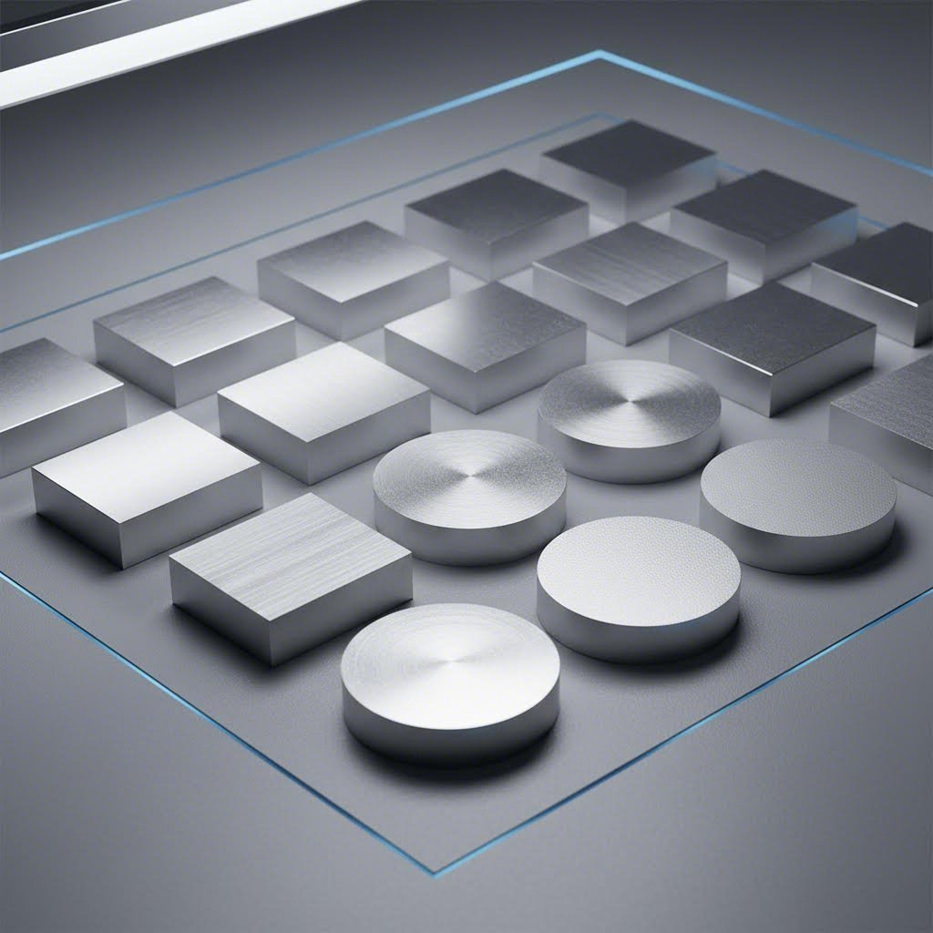
When you define aluminum extrusion, you're describing a transformation process. Cylindrical aluminum billets are first preheated to temperatures between 400-480°C (750-900°F). At this range, the metal becomes soft and malleable without actually melting. A powerful hydraulic ram then pushes this softened aluminum through a precision-engineered die, much like toothpaste through a tube.
The aluminium extrusion process unfolds in several key stages:
Here's where things get interesting for designers. When creating aluminum extrusion profiles, you're not just drawing shapes—you're engineering metal flow. The aluminum separates around internal die features called mandrels, then welds back together under immense pressure to form hollow sections. This solid-state welding happens naturally during the process, creating seamless tubes and complex multi-void geometries.
The beauty of aluminum extrusion design lies in its versatility. You can incorporate screw bosses, snap-fit connections, heat sink fins, and structural ribs—all in a single profile. This consolidates multiple parts into one, slashing assembly time and reducing potential failure points.
Understanding how aluminum extrusion actually works fundamentally changes how you approach CAD decisions. When you know that wall thicknesses need balance, that sharp corners create die stress, and that hollow sections require special tooling, you start designing smarter from the first sketch.
Designers who understand extrusion constraints don't just avoid manufacturing problems—they unlock geometric possibilities their competitors never knew existed.
This guide bridges the gap between basic introductions and dense technical references. You'll find the practical specifications, alloy comparisons, and design-for-manufacturability insights that typically require consulting multiple sources. Whether you're optimizing an existing aluminum extrusion or creating something entirely new, these principles will help you avoid costly mistakes and get designs right the first time.
Here's a question most designers don't ask early enough: which alloy should I specify? Many engineers select 6061 or 6063 based on habit or vague recommendations, never realizing how profoundly this choice affects everything from achievable wall thickness to final surface appearance. The aluminum extrusion alloys you specify don't just determine mechanical properties—they fundamentally shape your design constraints.
Think of it this way: choosing an alloy before understanding your design requirements is like selecting a foundation material before knowing how many stories your building will have. Let's fix that approach.
All common extrusion alloys belong to the 6000 series, meaning they share magnesium and silicon as primary alloying elements. These form magnesium silicide (Mg₂Si), which provides the strength and corrosion resistance you're counting on. However, the specific ratios—plus trace elements like manganese and copper—create dramatically different aluminum extrusions for different applications.
When evaluating aluminium extrusion types, consider these key factors:
These factors interconnect in ways that surprise many designers. For instance, the same chemical properties that make 6063 easier to extrude also produce superior anodized finishes—but at the cost of roughly 12% lower tensile strength compared to 6061.
Let's examine the two most popular types of aluminum extrusions side by side. Understanding their differences helps you make smarter CAD decisions from the start.
6063 ("Architectural Aluminum") contains 0.45-0.9% magnesium and 0.2-0.6% silicon—lower concentrations than 6061. This chemistry makes it the undisputed champion of extrudability. You'll achieve thinner walls, tighter corner radii, and more complex geometries with 6063. The lower alloying content also means better corrosion resistance and exceptional surface quality that anodizes beautifully.
However, 6063-T6 delivers approximately 240 MPa yield strength versus 6061-T6's 276 MPa. That 15% strength difference matters for structural applications.
6061 ("Structural Aluminum") contains higher magnesium (0.8-1.2%) plus copper (approximately 0.28%). The copper addition boosts strength and machinability but slightly reduces corrosion resistance and makes extrusion more challenging. Expect thicker minimum walls and less forgiving geometry constraints when specifying standard aluminum extrusions in 6061.
The practical impact? A complex heat sink design that extrudes perfectly in 6063 might require wall thickness increases of 20-30% in 6061 to achieve reliable production. Your aluminum extrusion tolerances may also widen slightly with the harder alloy.
Before diving into the comparison table, ask yourself these questions:
Your answers point toward specific alloys. Here's how the most common options compare for extruded aluminum profiles:
| Alloy | Typical Applications | Min. Wall Thickness | Extrudability | Surface Finish Quality |
|---|---|---|---|---|
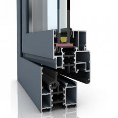
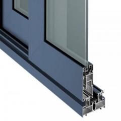
| 6063-T6 | Window frames, door systems, architectural trim, decorative applications | 0.040" (1.0mm) for small profiles | Excellent | Excellent—ideal for anodizing |
| 6061-T6 | Structural frames, aerospace fittings, automotive components, CNC machined parts | 0.050"-0.062" (1.3-1.6mm) typical | Good | Good—moderate anodizing quality |
| 6005-T5 | Rail car structures, truck frames, modular framing systems | 0.045"-0.055" (1.1-1.4mm) | Good | Good—suitable for industrial use |
Notice the pattern? Alloys with better extrudability support thinner walls and produce better surface finishes. This isn't coincidence—the same material properties that allow aluminum to flow smoothly through complex dies also reduce surface defects and enable finer geometries.
For most applications, 6063 represents the default choice unless you specifically need 6061's higher strength or better machinability. In fact, industry data shows the 6000 series accounts for roughly 75% of all extrusion applications, with 6063 being the single most popular alloy.
When strength requirements fall between 6063 and 6061, consider 6005 as a middle-ground option. It offers approximately 260 MPa yield strength—matching 6061 in many tempers—while maintaining better extrudability than 6061. This makes it popular for structural extrusions where surface finish matters but ultimate strength isn't critical.
Now that you understand how alloy selection shapes your design constraints, the next step is translating that knowledge into specific dimensional specifications.
You've selected your alloy. Now comes the question that separates successful aluminum extrusion profile designs from costly failures: what dimensions can you actually achieve? The answer isn't as simple as checking a single chart. Your aluminum extrusion dimensions depend on profile complexity, alloy selection, and how different features interact within your design.
Let's break down the specific numbers you need—starting with the dimension that causes the most manufacturing headaches.
Here's a reality check: that ultra-thin wall you sketched in CAD might not survive the extrusion process. Minimum wall thickness isn't arbitrary—it's governed by physics. Thinner walls create higher friction ratios, making it harder for aluminum to "break out" through the die. Push too thin, and you'll get incomplete fills, surface defects, or outright production failures.
The minimum achievable wall thickness depends primarily on your profile's circumscribing circle (CC)—the smallest circle that completely encloses your cross-section. Larger profiles require proportionally thicker walls because the aluminum must flow greater distances while maintaining structural integrity.
According to industry specifications, here's what you can realistically achieve with extruded aluminum sizes:
| Circumscribing Circle (inches) | Solids & Semi-Hollows | Class 2 Hollow Shapes |
|---|---|---|
| 0.5 to under 2 | 0.040" | 0.055" |
| 2 to under 3 | 0.045" | 0.062" |
| 3 to under 4 | 0.050" | 0.078" |
| 4 to under 5 | 0.062" | 0.094" |
| 5 to under 6 | 0.078" | 0.110" |
| 6 to under 8 | 0.094" - 0.110" | 0.125" - 0.140" |
| 8 to under 12 | 0.125" - 0.172" | 0.156" - 0.220" |
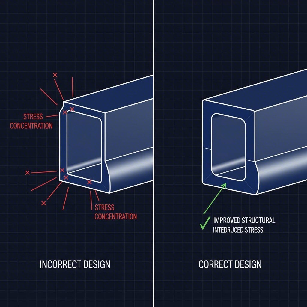
Notice hollow shapes require significantly thicker walls than solid profiles at every size. Why? The die must include internal mandrels that create stress concentrations and restrict metal flow. If you're designing standard aluminum extrusion profiles with internal voids, plan for 25-40% thicker walls compared to solid equivalents.
One critical rule often overlooked: adjacent wall thickness ratios greater than 2:1 invite trouble. Imagine one wall at 0.080" meeting another at 0.200"—the dramatic difference creates uneven cooling rates and metal flow speeds. The result? Warping, dimensional inconsistencies, and potential die failures. When walls of different thicknesses must meet, taper the transition gradually.
Sharp corners look clean on screen. In the extrusion press? They're production nightmares. Every internal corner creates a stress concentration in the die, while external corners cause aluminum flow disruptions that produce streaking and surface defects on adjacent faces.
The minimum corner radius depends on your wall thickness and profile complexity. As a baseline:
Here's why this matters beyond manufacturability: internal corners with proper radii can actually increase section strength by reducing stress concentrations during service. You're not just designing for production—you're improving performance.
For extruded aluminum sections requiring premium surface finishes (anodized architectural components, for example), specify even larger radii. The smoother the aluminum flows through the die, the fewer surface imperfections appear on your finished part.
When you're designing aluminum extrusions that must mate with other components or fit into assemblies, tolerance specifications become critical. The Aluminum Association publishes standard tolerance tables covering dimensional accuracy, straightness, twist, and flatness—but understanding which class applies to your project requires careful consideration.
Standard tolerances represent what any competent extruder achieves under normal production conditions. Precision tolerances require additional care, slower extrusion speeds, and often higher costs. Here's how key aluminum extrusion sizes and specifications typically break down:
| Dimension Type | Standard Tolerance | Precision Tolerance | Design Consideration |
|---|---|---|---|
| Wall Thickness | ±0.012" to ±0.024" | ±0.006" to ±0.012" | Thinner walls = tighter percentage variation |
| Metal Dimensions (width/height) | ±0.012" to ±0.030" | ±0.008" to ±0.015" | Increases with profile size |
| Space Dimensions (voids) | ±0.015" to ±0.035" | ±0.010" to ±0.020" | Hollow sections harder to control |
| Straightness | 0.004"/ft to 0.012"/ft | 0.002"/ft to 0.006"/ft | Asymmetric shapes twist more |
| Flatness (for flat surfaces) | 0.004" to 0.012" per inch width | 0.002" to 0.006" per inch width | Wide, thin sections most challenging |
For context, consider 2020 extrusion dimensions—the popular 20mm x 20mm modular framing standard. These profiles typically hold dimensional tolerances of ±0.2mm on major dimensions, with T-slot widths controlled to ±0.1mm to ensure accessory compatibility.
Two concepts help you predict whether your design will achieve target tolerances: tongue ratio and gap ratio.
The tongue ratio applies to protruding features (fins, ribs, flanges). Calculate it by dividing the protrusion length by its base width. Ratios exceeding 3:1 become increasingly difficult to produce with consistent dimensions—the unsupported tongue deflects during extrusion and cooling.
The gap ratio determines whether a partially enclosed void classifies as semi-hollow. You calculate it by dividing the void area by the square of the gap opening. According to published guidelines, gap ratios above 2.0-4.0 (depending on gap width and symmetry) push profiles into semi-hollow classification, requiring more complex dies and affecting achievable tolerances.
Why does classification matter? Semi-hollow and hollow profiles require porthole or bridge dies where aluminum splits around mandrels and welds back together. These weld lines can affect both mechanical properties and surface appearance—factors you'll want to consider when positioning critical features.
With dimensional constraints established, the next step is understanding how these specifications interact with profile shape classifications.
You've nailed your alloy selection and understand dimensional constraints. Now here's the question that determines your tooling costs, production speeds, and design flexibility: what shape classification does your profile fall into? The aluminum extrusion shapes you design aren't just geometric decisions—they fundamentally dictate which type of die you'll need and how much you'll pay to produce it.
Sounds like manufacturing minutiae? Consider this: a hollow profile might cost 40-60% more in tooling than a comparable solid design. Understanding these classifications before you finalize your CAD model prevents expensive redesigns later.
Every extruded aluminum shape falls into one of three categories, each with distinct die requirements and design implications. Let's examine what separates them.
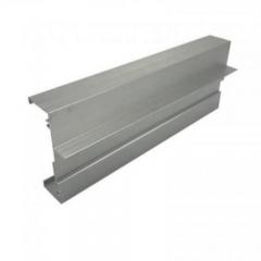
Solid Profiles
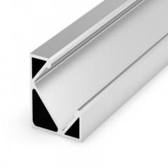
These are the simplest extruded shapes—no enclosed voids or openings. Think angles, channels, flat bars, and I-beams. The aluminum flows straight through the die opening without splitting around internal features.
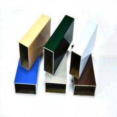
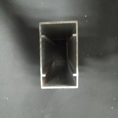
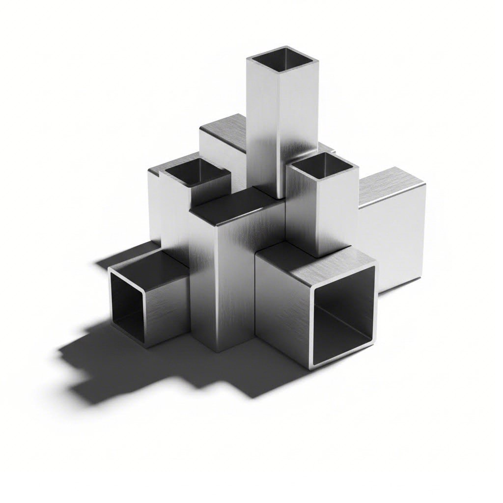
Hollow Profiles
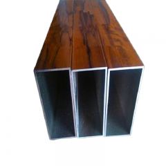
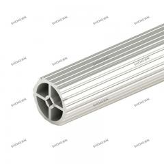
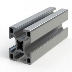
These types of aluminum extrusion feature one or more fully enclosed voids—rectangular tubes, round pipes, and complex multi-void sections like T-slot framing. Creating internal cavities requires specialized porthole dies with mandrels.
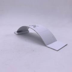
Semi-Hollow Profiles
Here's where classification gets tricky. Semi-hollow extrusion shapes have partially enclosed voids—channels with narrow gaps, C-sections, or profiles with deep grooves. They occupy the middle ground between solid and hollow complexity.
How do you know if your partially enclosed shape qualifies as semi-hollow? The tongue ratio formula provides the answer: (Void Area) ÷ (Gap Width)². When this ratio exceeds certain thresholds (typically 1.5 to 3.0 depending on gap size), your profile shifts from solid to semi-hollow classification. The larger the void area relative to the opening, the more difficult the shape becomes to extrude.
Beyond the basic solid/hollow/semi-hollow distinction, the Aluminum Association further classifies hollow profiles into classes that affect tolerance expectations and production considerations.
Class I Hollows feature balanced, round internal voids larger than 1 inch in diameter. These are the easiest hollow aluminum extrusions shapes to produce because the mandrel experiences uniform pressure from all directions.
Class II Hollows include smaller voids (under 5 inches with walls over 0.11 inches) and asymmetric internal geometries. The uneven stress distribution requires more robust die design and may limit achievable tolerances.
Class III Hollows represent the most challenging category—large, complex multi-void sections or profiles with very thin internal features. Expect higher tooling costs and potentially longer lead times.
Why should designers care about these classifications? Because they directly predict:
Understanding die design fundamentals—even at a basic level—transforms how you approach aluminum extruded shapes. You're not just drawing profiles; you're engineering metal flow.
During extrusion, aluminum enters the die as a solid cylinder and must redistribute itself to fill your profile's cross-section. Simple, symmetric shapes allow uniform flow. Complex geometries with varying wall thicknesses, deep pockets, or asymmetric features create uneven flow velocities—and that's where problems begin.
Consider a hollow rectangular tube with one thick wall and three thin walls. The aluminum naturally flows faster through the path of least resistance (the thick wall area). Without careful die design, the thin walls fill incompletely or experience surface defects. Die makers compensate using variable bearing lengths—essentially controlling flow speed by adjusting how far aluminum must travel through different die sections.
From a designer's perspective, this means:
Here's a practical example: imagine you've designed a sophisticated electronics enclosure as a single multi-void hollow profile. The die requires multiple mandrels, precise bearing adjustments, and expensive H13 steel tooling. Production runs slowly, and die life may be limited.
Alternative approach? Split the enclosure into a base channel (semi-hollow) and a cover (solid or simple hollow). Each profile uses simpler, cheaper dies. Assembly adds a step, but you've reduced tooling investment by potentially 50% while improving production reliability.
This design-for-manufacturability mindset separates engineers who consistently deliver successful extrusion projects from those who fight recurring production issues. The die doesn't care how elegant your CAD model looks—it only responds to physics.
With shape classifications and their manufacturing implications clear, you're ready to tackle the specific design mistakes that derail even experienced engineers.
You've learned the rules. Now let's talk about what happens when designers break them—sometimes unknowingly, sometimes thinking they know better. Following an aluminum extrusion design guide doesn't guarantee success if you don't understand why each guideline exists. The engineers who consistently deliver successful projects aren't just following checklists; they've internalized the physics behind every recommendation.
Here's what separates expensive failures from first-run successes: understanding that every design decision creates downstream consequences in the extrusion press, the finishing line, and ultimately in your product's performance.
Wall thickness errors cause more rejected designs than any other single factor. The frustrating part? Most are entirely preventable with basic aluminum extrusion design guidelines awareness.
Mistake #1: Specifying walls thinner than the alloy can support
Why it happens: Designers optimize for weight reduction or material cost without consulting minimum thickness tables. That 0.035" wall looks great in CAD until the extruder explains it won't reliably fill a 4-inch circle profile in 6061.
Why it matters: Undersized walls create incomplete fills, surface tearing, and inconsistent dimensions. Even when production "succeeds," thin areas experience accelerated cooling that introduces residual stresses and warping.
Mistake #2: Creating dramatic thickness variations within a single profile
Why it happens: Structural requirements demand thick sections for load-bearing areas while aesthetic or weight goals push other areas thin. A 3:1 or greater thickness ratio seems reasonable on paper.
Why it matters: Aluminum flows faster through thick sections (less friction) and slower through thin areas. This velocity differential creates uneven pressure on the aluminum extrusion die, causing deflection, premature wear, and dimensional inconsistencies. During cooling, thick sections shrink more than thin ones, introducing warping and internal stresses.
Mistake #3: Ignoring how wall thickness affects post-extrusion operations
Why it happens: The focus stays on extrusion success while forgetting that most profiles require cutting, drilling, or machining afterward. Understanding how to cut aluminum extrusion properly requires adequate material for tool engagement.
Why it matters: Thin walls vibrate during machining, creating chatter marks and dimensional variations. Drilling too close to edges causes blowout. Cutting thin-walled hollow sections can collapse the profile if fixturing isn't carefully designed.
Sharp corners look clean in CAD software. In the real world of metal flow and stress distribution, they're failure points waiting to happen. Proper aluminium extrusion design guidelines emphasize generous radii for good reason.
Mistake #4: Specifying sharp internal corners
Why it happens: Designers think in terms of finished part appearance rather than manufacturing physics. Right-angle intersections seem structurally sound and aesthetically clean.
Why it matters: Internal corners create stress concentrations in the die steel—exactly where the tool is weakest. Sharp corners also restrict aluminum flow, causing the metal to "hang up" and create surface defects on adjacent walls. According to industry research, sharp corners should be avoided whenever structural requirements permit alternative solutions.
Mistake #5: Ignoring external corner radius requirements
Why it happens: External corners seem less critical than internal ones since there's no enclosed stress concentration.
Why it matters: Aluminum flowing around sharp external corners creates turbulence that marks the surface—streaking, orange peel texture, or visible flow lines. These defects become especially apparent after anodizing or painting.
Mistake #6: Abrupt transitions between different wall thicknesses
Why it happens: Space constraints or functional requirements seem to demand sudden thickness changes.
Why it matters: Step changes create weld line-like flow patterns where fast-moving and slow-moving aluminum meet. The interface often shows as a visible line on the finished surface. Structurally, abrupt transitions concentrate stress at the junction during service loading.
Asymmetric profiles aren't impossible—but they're harder to extrude, harder to straighten, and harder to hold to tolerance. Understanding why helps you make informed trade-offs.
Mistake #7: Designing asymmetric profiles without compensating features
Why it happens: Functional requirements legitimately demand asymmetry—a mounting channel on one side, a heat sink fin array that faces a specific direction, or an aesthetic feature that can't be mirrored.
Why it matters: Asymmetric profiles experience uneven cooling rates and differential shrinkage. One side contracts more than the other, introducing bow, twist, or camber that complicates straightening. Achieving flatness tolerances on asymmetric wide sections can be especially challenging.
Mistake #8: Positioning critical features at profile extremities
Why it happens: Functional requirements place screw bosses, snap fits, or precision surfaces at the edges of the cross-section.
Why it matters: Profile extremities experience the greatest dimensional variation during extrusion and cooling. They're furthest from the neutral axis and most affected by twist or bow. Precision features located here will show maximum tolerance variation piece-to-piece.
Mistake #9: Overlooking thermal expansion in assembly design
Why it happens: Designers focus on room-temperature fit without considering operational temperature ranges. Aluminum's coefficient of thermal expansion (approximately 23 µm/m·°C) is roughly twice that of steel.
Why it matters: An aluminum profile firmly bolted to a steel frame at 20°C will experience significant stress at 60°C. Outdoor applications see even greater temperature swings. Trapped thermal expansion causes buckling, joint failure, or fastener pull-out.
These nine mistakes represent the most common failure modes we see in aluminum extrusion projects. Notice the pattern: most errors stem from applying general mechanical design thinking without understanding extrusion-specific constraints. The aluminum extrusion die doesn't care about your design intent—it only responds to physics.
Master these fundamentals, and you'll avoid the costly iterations that plague your competitors. The next consideration? Understanding how your design decisions directly impact project economics.
Here's the conversation most extrusion suppliers avoid: how do your design choices actually affect project costs? While competitors focus purely on technical specifications, understanding the economics behind your aluminum extrusion frame design separates good engineers from great ones. Every line you draw in CAD has a dollar sign attached—sometimes a small one, sometimes surprisingly large.
The good news? Unlike casting or injection molding, aluminum extrusion offers remarkably accessible tooling costs. According to industry analysis, while casting tools can exceed $30,000, custom extrusion dies often cost under $1,000. That's a 30x difference in initial investment. But here's what most guides won't tell you: small design decisions can swing your tooling costs by 50% or more within the extrusion category itself.
Think of die cost as a direct reflection of manufacturing difficulty. The more challenges your profile presents to the die maker, the higher your tooling investment climbs. Understanding this relationship helps you make informed trade-offs during the design phase.
For structural aluminum extrusions, typical custom die costs break down as follows:
Notice the pattern? Each step up in shape classification adds roughly 15-25% to your tooling cost. A seemingly minor design decision—converting a solid mounting rail into a hollow tube for weight reduction—might add $300-500 to your die investment.
Beyond basic classification, specific design features compound costs:
Here's a practical example: imagine you're designing an extruded aluminum framing system for modular enclosures. Your initial concept features a complex hollow profile with integrated T-slots on all four sides, internal cable channels, and decorative external ribs. The die estimate comes back at $2,800.
Alternative approach? Split the design into a simpler four-slot hollow base ($1,400 die) plus a snap-on rib cover ($900 die). Total tooling: $2,300—and you've gained the flexibility to offer covered or exposed versions without additional tooling investment.
Tooling is a one-time expense. Per-unit production costs, however, compound across every piece you order. Smart design decisions here create lasting savings that grow with your production volumes.
Raw material typically accounts for approximately 90% of basic extrusion costs, according to manufacturing analysis. This means weight optimization delivers outsized returns. But here's the nuance: blindly minimizing material often backfires. Walls that are too thin slow extrusion speeds, increase scrap rates, and may require more expensive alloys.
The following design factors directly influence per-unit economics:
Consider die life as a hidden per-unit cost factor. A complex die with thin unsupported sections might require replacement every 50,000 feet of extrusion. A simpler, more robust die producing the same profile with minor design modifications might last 150,000 feet. That die replacement cost—amortized across production—directly affects your piece price.
Secondary operations represent another major cost lever. According to industry research, although individual complex extrusions might cost more than simple formed sheet steel parts, overall system costs often decrease because the extrusion process eliminates numerous secondary operations. Every hole you integrate into the profile is a hole you don't drill later. Every snap-fit connection is a fastener you don't purchase and install.
Every aluminum framing extrusion project involves trade-offs. The goal isn't minimizing cost at any price—it's optimizing value for your specific requirements. Understanding which design elements drive costs helps you allocate budget where it matters most.
Start by categorizing your requirements into three tiers:
With requirements prioritized, apply cost-conscious design principles systematically:
For structural aluminum framing applications: Optimize rib placement and wall thickness for load requirements rather than arbitrary minimums. A profile that's 5% heavier but extrudes 15% faster represents genuine cost savings at volume.
For aesthetic applications: Invest in alloy selection and surface finish rather than geometric complexity. A simple 6063 profile with premium anodizing often outperforms a complex shape with standard finish—at lower total cost.
For prototype or low-volume runs: Accept slightly higher per-unit costs in exchange for simpler tooling. That $500 die savings matters more when you're only ordering 1,000 pieces than when you're ordering 100,000.
One often-overlooked strategy: discuss your cost constraints openly with your extrusion partner. Experienced engineers at quality suppliers can frequently suggest design modifications that maintain function while significantly reducing tooling or production costs. They've seen thousands of profiles and understand where complexity adds value versus where it simply adds expense.
With cost implications clear, the next consideration is how your design decisions affect surface treatment options and achievable finish quality.
You've optimized your aluminum profile extrusion for manufacturability and cost. But here's what many designers overlook: your geometry decisions made chapters ago now determine which surface finishes are achievable—and how good they'll actually look. The relationship between design geometry and finish quality is something competitors rarely explain, yet it directly impacts your product's durability and market appeal.
Whether you're specifying aluminum extrusion rails for architectural applications or industrial aluminium extrusion profiles for machinery, understanding this connection prevents disappointing results after production is already underway.
Each aluminum extrusion application demands specific performance characteristics from its surface treatment. The right choice depends on your operating environment, aesthetic requirements, and budget constraints.
Anodizing creates a durable oxide layer through an electrochemical process. The aluminum itself converts to aluminum oxide, becoming part of the substrate rather than sitting on top. This integration provides excellent abrasion resistance and corrosion protection. According to industry analysis, anodizing is particularly known for its excellent weather resistance and the hardness of the anodic film, making it beneficial for outdoor applications.
Powder coating applies dry powder electrostatically, then cures it under heat to form a tough, uniform film. This process produces thicker, more protective layers than traditional liquid painting while emitting minimal volatile organic compounds. The coating thickness and uniformity ensure comprehensive coverage, reducing corrosion and wear risks significantly.
PVDF (Polyvinylidene Fluoride) coatings deliver exceptional weathering resistance for demanding architectural applications. These fluoropolymer finishes maintain color stability and gloss retention for decades, even under intense UV exposure. Premium building facades and curtain wall systems frequently specify PVDF for this reason.
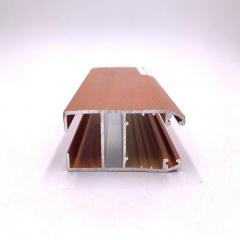
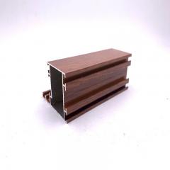
Specialized treatments like micro-arc oxidation create ceramic-like surfaces with extreme hardness—useful for high-wear industrial components. Brushed, polished, and wood-grain finishes address specific aesthetic requirements across various types of extruded aluminum.
Here's what your competitors aren't telling you: the surface quality of an extruded aluminum profile depends on die condition, profile design, production conditions, and alloy selection. According to Hydro's technical documentation, various surface defects—such as extrusion lines that are process-related—occur when the profile emerges from the die. These defects appear to varying degrees in all surface classes, creating the typical "extrusion appearance."
Your design decisions directly influence how pronounced these inherent characteristics become:
For premium surface finishes, design for smooth aluminum flow. Generous corner radii, balanced wall thicknesses, and symmetric geometries all contribute to cleaner as-extruded surfaces that finish beautifully.
Selecting the right treatment involves balancing durability needs, aesthetic goals, and geometric constraints. This comparison helps you match aluminum extrusion applications to appropriate finishes:
| Treatment Type | Durability Rating | Color Options | Design Geometry Considerations |
|---|---|---|---|
| Anodizing | Excellent hardness; integral to substrate | Limited palette; metallic tones; custom colors available | Requires smooth surfaces; sharp corners show streaking; avoid dramatic thickness changes |
| Powder Coating | Superior impact and corrosion resistance; thicker than paint | Unlimited colors; textures; metallics; special effects | Recesses need minimum 0.25" opening for coverage; sharp internal corners trap powder |
| PVDF Coating | Exceptional UV and weather resistance; 20+ year lifespan | Wide range; excellent color retention | Similar to powder coating; premium cost justifies simpler geometries |
| Micro-arc Oxidation | Ceramic-like hardness; extreme wear resistance | Limited; typically gray/black tones | Works best on simpler profiles; complex shapes increase processing difficulty |
Notice the pattern? Simpler geometries consistently achieve better finish results across all treatment types. When your extruded aluminum profile demands premium appearance, invest design effort in smooth-flowing shapes rather than complex features that compromise surface quality.
For projects requiring both aesthetic excellence and functional complexity, consider Shengxin Aluminium's comprehensive surface treatment capabilities. Their offerings include anodizing in custom colors like Champagne and Rose Gold, powder coating, PVDF, and micro-arc oxidation—all backed by technical support that helps match your design geometry to achievable finish quality.
With surface treatment considerations integrated into your design process, the final step is validating your complete design before submission to manufacturing.
You've absorbed the principles. You understand alloy selection, dimensional constraints, shape classifications, and cost implications. Now comes the moment of truth: is your design actually ready to send to an extrusion partner? This is where many aluminum extrusion projects stumble—not from poor design concepts, but from incomplete preparation that forces costly revisions after tooling has already begun.
What are aluminum extrusions used for if not bringing your engineering vision to life? Whether you're creating extruded structural aluminum for industrial machinery or an aluminum frame structure for architectural applications, the same validation principles apply. The following checklist transforms scattered design knowledge into a systematic pre-submission process that catches problems before they become expensive mistakes.
Before your CAD file ever reaches a manufacturer, run through this sequential validation process. Each step builds on the previous one, ensuring you've addressed every critical factor that affects manufacturability.
With design validation complete, ensure your documentation package includes everything your extrusion partner needs to quote accurately and begin production without delays.
| Documentation Element | Required Details | Common Omissions to Avoid |
|---|---|---|
| CAD Files | 2D cross-section with dimensions; 3D model if available | Missing tolerances; unlabeled critical dimensions; outdated revision |
| Material Specification | Alloy designation and temper (e.g., 6063-T5) | Specifying alloy without temper; generic "aluminum" callout |
| Length Requirements | Finished length; cut tolerance; end preparation | Forgetting to specify deburring or end squareness requirements |
| Quantity and Schedule | Initial order; projected annual volume; delivery timeline | Not requesting price breaks for volume growth |
| Surface Treatment | Treatment type; color specification; coverage requirements | Assuming "anodized" is sufficient without specifying type or thickness |
| Secondary Operations | Machining drawings; hole patterns; bending specifications | Providing extrusion drawing only without fabrication details |
According to experienced extruders, designers should start with a basic sketch or detailed CAD file specifying ideal dimensions and tolerances, identify the aluminum alloy and temper, highlight cosmetically important surfaces, and specify any required coatings. This comprehensive approach prevents back-and-forth clarification that delays your project.
The last step before submission involves stepping back from technical details to consider the complete aluminum extrusion project holistically. Ask yourself these questions:
Working with experienced extrusion partners streamlines the transition from design to manufacturing-ready specifications. Shengxin Aluminium, with their 35 advanced extrusion presses ranging from 600T to 5500T capacity, provides end-to-end technical support from die development through mass production. Their state-of-the-art CNC machining centers handle precise cutting, drilling, and bending to meet exact specifications—turning your validated design into finished components without the coordination headaches of managing multiple vendors.
For extrusion aluminum projects requiring complex secondary operations, integrated deep processing capabilities eliminate handoff delays and dimensional drift between suppliers. When your aluminum extrude design includes holes, slots, miters, or bends, having these operations performed by the same partner who produced the profile ensures consistent quality and faster delivery.
The designers who consistently deliver successful aluminum extrusion projects share one trait: they validate systematically before submitting. This checklist transforms scattered knowledge into actionable verification steps. Use it for every project, and you'll avoid the costly iterations that plague your competitors while building lasting partnerships with manufacturing partners who appreciate well-prepared designs.
Successful aluminum extrusion design requires uniform wall thickness (keeping adjacent wall ratios below 2:1), rounded corners (internal radii at least 0.5x wall thickness), symmetrical profiles for easier production, and proper alloy selection matching your application needs. Avoid deep narrow channels, specify minimum 0.020" external corner radii, and consider how your geometry affects surface finish quality. Working with experienced partners like Shengxin Aluminium provides technical support from die development through production.
Start by determining your circumscribing circle size and selecting an appropriate alloy (6063 for complex geometries, 6061 for structural strength). Keep shapes as symmetrical as possible with outside corners at minimum 0.020". Verify wall thickness meets minimums for your profile size—typically 0.040" to 0.172" depending on circumscribing circle diameter. Calculate tongue ratios for semi-hollow features and ensure thickness transitions taper gradually rather than stepping abruptly.
ASTM B221 is the primary standard specification for aluminum and aluminum-alloy extruded bars, rods, wire, profiles, and tubes. This standard covers chemical composition, mechanical properties, dimensional tolerances, and testing requirements. When specifying aluminum extrusions, reference ASTM B221 alongside Aluminum Association tolerance tables to ensure your design meets industry-accepted manufacturing standards for your chosen alloy and temper.
Minimum wall thickness depends on your profile's circumscribing circle and shape classification. For profiles under 2" diameter, solid shapes can achieve 0.040" walls while hollow shapes require 0.055" minimum. Larger profiles (8-12" diameter) need 0.125-0.172" for solids and 0.156-0.220" for hollows. Alloy choice also matters—6063 achieves thinner walls than 6061. Always add 10-15% safety margin for complex geometries.
Profile complexity directly impacts tooling investment and production economics. Solid profile dies cost $1,250-$1,500, semi-hollow dies run $1,400-$1,700, and hollow profile dies range $1,500-$1,950+. Additional features like multiple hollows, tight internal corners, and asymmetric geometry compound costs further. However, integrating features like screw bosses and snap-fits into extrusions often reduces total system cost by eliminating secondary machining operations.


 serviço on-line
 0086 136 3563 2360
 sales@sxalu.com
 +86 136 3563 2360
 português
 English
 français
 Deutsch
 русский
 español
 العربية
 ไทย
ไทย Việt
Việt Українська