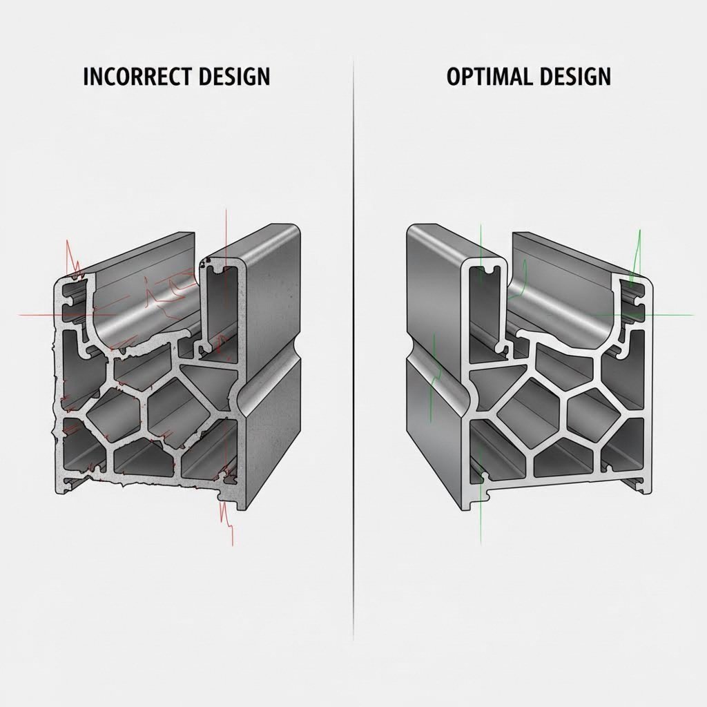
When you design aluminum extrusion profiles, you're not just sketching shapes on paper. You're making decisions that will echo through every stage of manufacturing, from die creation to final delivery. Understanding this process from the start can save you thousands of dollars and months of frustration.
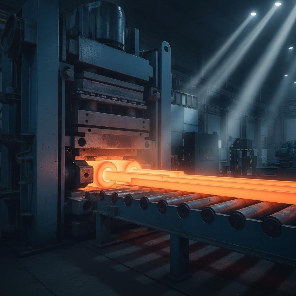
So, what exactly is aluminum extrusion? To define extruded aluminum simply: it's a manufacturing process where heated aluminum billets are forced through a specially shaped die opening under immense pressure, typically ranging from 1,000 to 15,000 tons. The aluminum emerges on the other side with a precise cross-sectional profile that matches the die's opening.
Think of it like squeezing toothpaste through a shaped nozzle. The nozzle determines the shape, and once you've committed to that nozzle, there's no changing the outcome mid-squeeze. This aluminium extrusion definition captures the core challenge: the die determines everything about your final profile's geometry.
The process itself involves preheating aluminum billets to around 700-930°F (370-500°C) to achieve the right plasticity. A hydraulic ram then pushes the softened metal through the die, creating profiles that can be solid, hollow, or semi-hollow depending on your design requirements.
Here's what separates aluminum extrusion from other manufacturing methods: once your die is made, changing course becomes expensive. Unlike machining, where you can adjust dimensions on the fly, extrusion design requires upfront planning because every aspect of your profile is locked in at the die stage.
Research from Carnegie Mellon University confirms that decisions made in the design process commit 70 to 80 percent of a product's total cost. For aluminum extrusion projects, this percentage can be even higher because die tooling represents a significant fixed investment.
This is why successful aluminum extrusion design isn't just about creating an attractive profile. It's about understanding how your design choices cascade into production outcomes:
Engineers, product designers, and procurement professionals who grasp this connection between design aluminum extrusion choices and production outcomes position themselves to communicate effectively with manufacturers. They ask better questions, provide clearer specifications, and ultimately receive profiles that match their expectations without costly redesigns.
Before you finalize any aluminum extrusion design, you need to understand which shape category your profile falls into. This classification isn't just academic terminology. It directly determines your die costs, production complexity, and manufacturing timeline. Let's break down the three main types of aluminum extrusions and explore how each category affects your project budget.
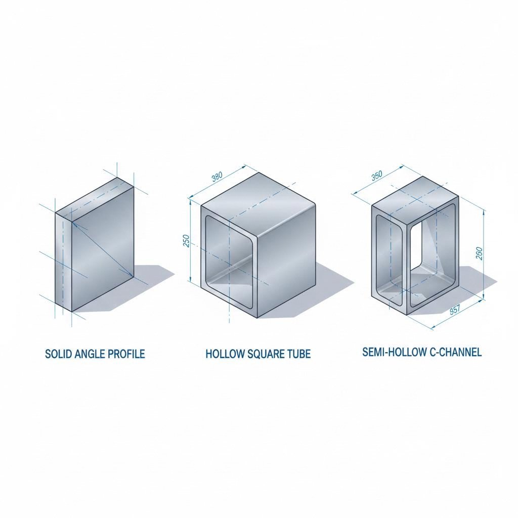
The extrusion industry classifies aluminum extrusions shapes into three primary categories based on their cross-sectional geometry. Each category requires different die construction methods, which is why shape classification matters for your bottom line.
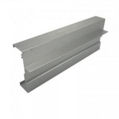
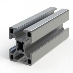
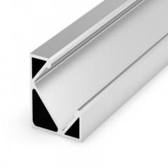
Solid shapes are the simplest to manufacture. These profiles have no enclosed voids or partially enclosed areas in their cross-section. Common examples include angles, flat bars, channels, and T-slots. Because solid dies are single-piece tools with no internal components, they cost less and typically last longer than more complex alternatives.
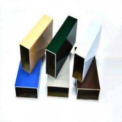
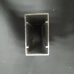
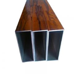
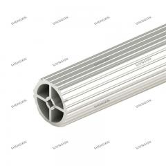
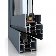
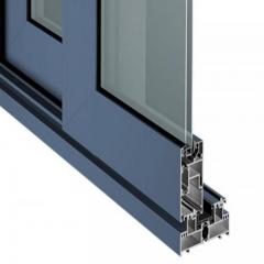
Hollow shapes completely enclose one or more voids within their cross-section. Think of square tubes, round pipes, or multi-chambered architectural profiles. According to the Bonnell Aluminum classification system, hollow shapes are further divided into three classes:
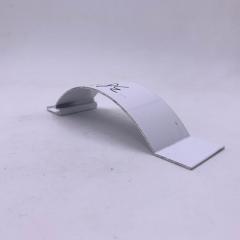
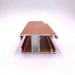
Semi-hollow shapes partially enclose a void without fully surrounding it. Picture a C-channel with a narrow opening or a mounting bracket with a deep groove. The classification depends on calculating the gap ratio: the area of the partially enclosed void divided by the square of the gap width. Semi-hollow profiles are categorized as Class 1 (symmetrical about the gap centerline) or Class 2 (asymmetrical or with uneven wall thicknesses).
Why does this classification system matter when you design aluminum extrusion profiles? Because die construction varies dramatically between categories. Solid dies are machined from a single piece of tool steel. Hollow dies require a mandrel and bridge assembly to create internal voids, increasing both material usage and precision machining time.
Here's how the aluminum extruded shapes you choose translate to tooling investment:
| Shape Type | Complexity Level | Typical Applications | Die Cost Range | Design Considerations |
|---|---|---|---|---|
| Solid | Low | Angles, channels, flat bars, T-slots, rails | Low ($300–$800) | Simplest to produce; longest die life (20,000–50,000 kg) |
| Semi-Hollow | Medium | Mounting brackets, C-channels, clips, edge trim | Medium ($800–$1,500) | Gap ratio determines classification; narrow openings increase difficulty |
| Hollow | High | Square/round tubes, structural tubing, heat sinks with internal channels | High ($1,000–$3,000+) | Requires mandrel and bridge; shorter die life (10,000–30,000 kg) |
When browsing any extruded aluminum shapes catalog, you'll notice that hollow profiles with multiple internal chambers command the highest tooling prices. Industry data shows multi-cavity hollow dies can reach $5,000 or more due to the complexity of balancing material flow across multiple voids simultaneously.
Understanding extrusion shapes also helps you identify cost-saving opportunities. Consider these common extruded aluminum shapes and their practical applications:
The key takeaway? Before committing to a custom profile, check whether a standard shape could meet your requirements. Standard aluminum extrusion shapes often have existing dies available, eliminating tooling costs entirely. When custom designs are necessary, understanding which shape classification your profile falls into helps you anticipate costs and communicate more effectively with your manufacturing partner.
Now that you understand how profile geometry affects tooling investment, the next critical design decision involves specifying appropriate wall thicknesses for your application.
Wall thickness is one of the most misunderstood aspects of aluminum extrusion design. Get it wrong, and you'll face production delays, quality issues, or unnecessarily high costs. Get it right, and your aluminum extrusion profiles will perform exactly as intended while staying within budget. Let's cut through the vague recommendations you've seen elsewhere and give you specifications you can actually use.
When specifying wall thickness for extruded aluminum sections, context matters. A decorative trim piece doesn't need the same robust walls as a load-bearing structural member. The following table provides actionable guidelines based on real-world application requirements:
| Application Type | Minimum Wall Thickness | Recommended Range | Key Considerations |
|---|---|---|---|
| Architectural | 1.0mm (0.040") | 1.0mm–2.0mm | Must support anodizing; surface finish critical |
| Structural | 1.5mm (0.060") | 1.5mm–4.0mm | Load calculations required; alloy strength matters |
| Industrial | Varies by load | 1.2mm–6.0mm+ | Engineering analysis needed for specific applications |
| Decorative | 0.7mm (0.028") | 0.7mm–1.2mm | Non-load-bearing only; limited post-processing options |
These aren't arbitrary numbers. According to industry tolerance standards, wall thickness tolerances typically run around ±10% of the nominal thickness. This means a 1.0mm wall could actually measure anywhere from 0.9mm to 1.1mm. For critical applications, factor this variation into your design calculations.
What determines your minimum wall thickness? Several factors work together:
Here's a practical example: A German LED lighting manufacturer approached an aluminum section supplier seeking thin wall extrusions at 0.7mm thickness with ±0.03mm tolerances. After technical evaluation, the manufacturer could achieve 0.7mm ±0.1mm, but the tighter tolerance wasn't feasible without costly secondary operations. For assembly-critical dimensions, European standard EN-755-9 provides realistic tolerance expectations that prevent such misalignments.
You might assume thicker walls are always safer. More material means more strength, right? Not exactly. Overspecifying wall thickness creates problems beyond just wasted aluminum.
First, consider extrusion speed. Thicker walls mean more material flowing through the die per second, which affects temperature management. According to extrusion process research, higher speeds with thick walls can cause dimensional distortion and surface quality issues. Manufacturers may need to slow production to maintain quality, increasing your per-foot costs.
Second, hollow profiles with thick walls create thermal challenges. During extrusion, heat builds up in enclosed sections. Walls that are too thick trap this heat, potentially causing internal voids or inconsistent material properties. The aluminum extrusion tolerances you specified become impossible to maintain.
Third, there's the weight penalty. In applications like transportation or portable equipment, every gram matters. Overengineered walls add weight that affects performance, fuel efficiency, or user experience.
Conversely, going too thin creates its own set of problems. Thin walls require more precise dies, which cost more and wear out faster. The extrusion process must run slower to prevent tearing or surface defects. And if your aluminum extrusion dimensions include tight tolerances on thin sections, expect rejection rates to climb.
The sweet spot? Work backward from your actual requirements. Define the loads, finishes, and assembly needs first. Then specify the minimum wall thickness that meets those requirements with an appropriate safety factor. For most extruded aluminum sizes in standard applications, this approach lands you in the 1.2mm to 2.5mm range, where production runs smoothly and costs stay reasonable.
With wall thickness specifications locked in, your next decision involves selecting the right aluminum alloy to deliver the mechanical properties your design requires.
You've determined your profile shape and specified appropriate wall thickness. Now comes a decision that will define your product's performance for years to come: which aluminum extrusion alloys should you specify? This choice affects everything from structural integrity to surface appearance, and getting it wrong means either overpaying for properties you don't need or underperforming in critical applications.
Not all aluminum extrusions are created equal. The alloy you choose determines how your profile behaves under load, how it responds to surface treatments, and how long it lasts in demanding environments. Among the various aluminium extrusion types available, four alloys dominate the extrusion industry: 6063, 6061, 6005, and 6082. Each belongs to the 6000 series (Al-Mg-Si alloys), but their different compositions create distinct performance characteristics.
| Alloy | Strength Level | Extrudability | Surface Finish Quality | Best Applications | Anodizing Response |
|---|---|---|---|---|---|
| 6063 | Medium (214 MPa yield) | Excellent | Excellent | Architectural profiles, window frames, decorative trim | Excellent; uniform oxide layer |
| 6061 | High (276 MPa yield) | Good | Good | Structural components, aerospace, marine applications | Good; slight color variation possible |
| 6005 | Medium-High (241 MPa yield) | Good | Good | Rail profiles, ladders, furniture tubing | Good |
| 6082 | High (250 MPa yield) | Moderate | Fair | Heavy-duty structural, bridges, offshore platforms | Fair; may require extra preparation |
What drives these differences? It comes down to chemistry. According to Gabrian International, 6063 contains 0.45-0.9% magnesium and 0.2-0.6% silicon, while 6061 contains 0.8-1.2% magnesium and 0.4-0.8% silicon. These seemingly small variations translate to significant real-world performance gaps.
When selecting aluminum extrusion alloys, consider these key criteria:
Most design aluminum extrusion decisions come down to choosing between these two workhorses. Here's how to make the call confidently.
Choose 6063 when: Your application prioritizes appearance over raw strength. Often called "architectural aluminum," 6063 aluminum alloy dominates window frames, door frames, curtain walls, and decorative applications. Its excellent extrudability means manufacturers can produce complex profiles with thin walls and intricate details. After anodizing, 6063 forms a dense, uniform aluminum oxide layer that resists weathering and maintains visual appeal for decades.
Choose 6061 when: Strength takes priority over surface aesthetics. Known as "structural aluminum," 6061 delivers approximately 30% higher yield strength than 6063. According to American Douglas Metals, this makes it ideal for aerospace components, marine fittings, heavy-duty frames, and any application where load-bearing capacity is critical. While 6061 can be anodized, expect slight variations in the oxide layer compared to 6063.
What about 6005? This alloy bridges the gap between 6063's extrudability and 6061's strength. It's particularly popular for rail profiles, ladder rails, and furniture tubing where moderate strength and good surface quality both matter. The 6005-T5 temper offers better extrusion characteristics than 6082 while still outperforming 6063 structurally.
Understanding these aluminium extrusion types before requesting quotes helps you communicate precisely with manufacturers. Rather than asking for "strong aluminum," you can specify "6061-T6 for structural load requirements" or "6063-T5 for anodized architectural applications." This clarity prevents miscommunication and ensures your extruded aluminum profiles arrive ready to perform as intended.
With your alloy selected, you're ready to move from design concepts to production-ready specifications. The next section walks you through the complete workflow that transforms your ideas into manufacturable profiles.
You've selected your shape classification, specified wall thicknesses, and chosen the right alloy. But how do these decisions come together into a profile that manufacturers can actually produce? The gap between a good design concept and a production-ready specification is where many aluminum extrusion projects stumble. Let's walk through the complete workflow that transforms your ideas into manufacturable profiles without costly surprises.
When you design aluminum extrusion profiles, you're creating more than just a shape. You're building a complete technical package that communicates your requirements to everyone involved in production. According to the Aluminum Extruders Council's Extrusion Manual, the best design outcomes happen when customers work collaboratively with extruders from the earliest stages. Here's the sequential workflow that experienced engineers follow:
What documentation do manufacturers need to quote and produce your profile? A complete submission package includes:
The extrusion aluminium process commits significant resources once die cutting begins. These five checkpoints help you catch issues before they become expensive problems:
Checkpoint 1: Cross-Section Review
Have you applied manufacturability principles? Check that wall thickness transitions are gradual, tongue ratios fall within acceptable ranges for your chosen alloy, and the profile fits within your manufacturer's press circle size capabilities. According to Orange Aluminum, dies for aluminum extrusion are produced as steel cylinders with openings matching your desired profile shape. Any geometry that weakens the die steel creates production problems.
Checkpoint 2: Tolerance Validation
Are your specified tolerances achievable and necessary? Standard industry tolerances from ASTM standards work for most applications. Cross-sectional dimension tolerances for profiles typically range from ±0.006" for dimensions under 0.124" to ±0.024" for dimensions between 2.000" and 3.999" on circumscribing circles under 10 inches. When tighter tolerances are truly required, expect to pay premium pricing for precision dies and slower extrusion speeds.
Checkpoint 3: Material Flow Analysis
Will aluminum flow evenly through your proposed die geometry? Uneven wall thicknesses, dead corners, and sharp transitions create flow imbalances. The result? Profiles that twist, bow, or exhibit inconsistent mechanical properties. Your manufacturer's engineering team should perform flow analysis before die cutting begins.
Checkpoint 4: Post-Processing Compatibility
Does your design accommodate planned secondary operations? If you'll machine holes, your walls need adequate thickness. If you'll bend the profile, certain radii work better than others. If anodizing is planned, confirm your alloy and wall thickness support uniform oxide formation.
Checkpoint 5: Assembly Verification
Will your extrusion actually fit with mating components? When profiles must interlock or fit precisely with other parts, tolerance stack-up analysis becomes critical. A dimension at the high end of its tolerance on one part combined with a dimension at the low end on its mate can create interference or gaps.
By completing these checkpoints before die development begins, you eliminate the most common causes of project delays and cost overruns. The aluminum profile extrusion process runs smoothly when manufacturers receive clear, complete, and technically sound specifications. Taking time upfront to extrude aluminum profiles correctly saves weeks of revision cycles and thousands in tooling modifications.
With your design workflow complete and specifications locked in, understanding how these choices affect your manufacturing costs becomes the next critical knowledge area.
Here's a truth that catches many engineers off guard: the decisions you make during the design phase determine up to 90% of your aluminum extrusion project costs. Not production volume. Not shipping distance. Not even material prices. Your design choices. Understanding this relationship between geometry and dollars can mean the difference between a project that stays on budget and one that spirals into redesign cycles and inflated quotes.
When manufacturers evaluate your aluminum extrusion die requirements, they're calculating more than just material costs. They're assessing how difficult your profile will be to produce consistently. According to industry analysis, profile geometry is the primary cost driver, with complexity levels directly correlating to tooling investment and production challenges.
What specific design elements trigger higher pricing? Let's break down the factors that affect your quote:
| Design Element | Cost Impact Level | Why It Matters | Cost-Saving Alternative |
|---|---|---|---|
| Multi-void hollow sections | High | Requires complex mandrel and bridge assembly; balancing material flow across multiple voids demands precision engineering | Reduce void count or use standard aluminium extrusions with proven die designs |
| Tight dimensional tolerances | High | Involves longer machining cycles, additional inspection checkpoints, and slower extrusion speeds | Apply precision tolerances only to assembly-critical dimensions; use standard tolerances elsewhere |
| Thin walls (under 1.0mm) | Medium-High | Requires more precise dies that wear faster; production must run slower to prevent tearing | Specify minimum feasible thickness (1.2-2.5mm) for standard production efficiency |
| Asymmetric profiles | Medium | Uneven metal flow causes warping during cooling; requires specialized handling | Design symmetrical shapes or balance mass distribution across the cross-section |
| Special alloy requirements | Medium | High-strength alloys like 7075 reduce die life by up to 30% due to increased wear | Use 6063 or 6061 unless specific mechanical properties demand specialty alloys |
| Sharp internal corners | Medium | Causes material buildup and requires additional EDM machining on dies | Incorporate radii of at least 0.5mm on all internal corners |
| Large circumscribing circle | Medium | Larger CCD requires bigger die blocks, more raw steel, and high-capacity press equipment | Keep profiles within 150mm CCD when possible; split larger designs into assemblies |
The relationship between die complexity and tooling investment follows a predictable pattern. Standard die costs range from $500 to $5,000 depending on complexity, a fraction of the $50,000+ required for casting or injection molding tools. However, within the aluminium extrusion process, that range varies dramatically based on your design decisions.
Consider the real numbers: A solid die for simple extruded aluminum channel shapes costs $300-$800 and typically lasts for 20,000-50,000 kg of extrusion. A multi-cavity hollow die can reach $5,000+ and may only last 10,000-30,000 kg before requiring replacement or refurbishment. When you calculate cost per kilogram of production, the economic impact of your design choices becomes clear.
Reducing costs doesn't mean compromising on performance. It means making informed trade-offs that deliver the functionality you need without paying for complexity you don't. Here are strategies that experienced engineers use to optimize their extrusion aluminum projects:
Here's a practical example of these principles in action. An industrial equipment manufacturer initially designed a machine frame using four separate extruded aluminum channel shapes that would be welded together. By redesigning the frame as two integrated hollow sections with built-in mounting features, they reduced die count from four to two, eliminated welding operations, and cut total production cost by 35%.
The amortization calculation also matters for budget planning. If your die costs $2,000 and you expect to extrude 40,000 kg over its lifetime, your tooling cost per kilogram is just $0.05. But if you're producing a small batch of 5,000 kg, that same die adds $0.40 per kilogram to your costs. Understanding this relationship helps you make informed decisions about when custom profiles make economic sense versus when standard shapes offer better value.
With cost factors clearly understood, knowing which design mistakes to avoid becomes equally important for protecting your budget and timeline.
Even experienced engineers make mistakes when they design aluminum extrusion profiles. The difference between a successful project and a costly failure often comes down to recognizing these pitfalls before production begins. Your manufacturer sees these errors repeatedly, and they wish more customers understood how to prevent them. Let's walk through the seven mistakes that kill extrusion projects and the straightforward strategies to avoid each one.
These aren't theoretical concerns. According to MMG Extrusion, these represent the most common design issues manufacturers encounter when receiving new profile specifications. Each mistake creates real consequences: rejected parts, production delays, or budget overruns that could have been prevented with better upfront planning.
Beyond these seven critical mistakes, several additional errors frequently appear in submitted designs. Understanding these helps you communicate more effectively with your manufacturing partner:
The good news? Every one of these mistakes is preventable. By submitting complete documentation, reviewing designs with your manufacturer before die development, and applying the principles covered throughout this guide, you position your project for success. The small investment of time in proper design pays dividends through reduced scrap rates, faster production, and parts that perform exactly as intended.
With these common pitfalls identified and prevention strategies in hand, the next consideration is how surface treatment requirements should influence your initial design decisions.
Surface treatment isn't something you figure out after your aluminum extruded profiles arrive at your facility. It's a decision that should shape your design from the very first sketch. Why? Because the finish you choose affects wall thickness requirements, alloy selection, and even profile geometry. Engineers who treat surface treatment as an afterthought often discover their carefully designed profiles can't achieve the finish quality they expected.
When you design aluminum extrusion profiles, your surface treatment choice influences manufacturability at every stage. According to BRT Extrusions, selecting the right finish is essential to ensure the desired aesthetic appeal, durability, and performance of extruded components. The following table compares the most common surface treatment options available for aluminum extrusion applications:
| Treatment Type | Durability Level | Aesthetic Options | Design Considerations | Best Applications |
|---|---|---|---|---|
| Anodizing (Standard) | High | Clear, bronze, black; metallic appearance preserved | Minimum 1.0mm wall thickness; 6063 alloy preferred; uniform wall sections produce consistent color | Architectural profiles, window frames, decorative trim |
| Anodizing (Color/Custom) | High | Wide color range including champagne, rose gold, blue, red | Alloy chemistry affects final color; design should avoid deep recesses where dye may pool | Consumer products, premium fixtures, branded components |
| Powder Coating | Very High | Virtually unlimited colors; matte, gloss, textured finishes | Allows thinner walls than anodizing; complex profiles need proper grounding points for electrostatic application | Outdoor furniture, appliances, industrial equipment |
| PVDF Coating | Excellent (20+ years) | Extensive colors; excellent gloss retention | Requires thorough surface preparation; minimum film thickness of 25-30 microns for exterior use | Architectural cladding, curtain walls, exterior building components |
| Micro-arc Oxidation | Superior | Limited colors; ceramic-like appearance | Creates thicker, harder oxide layer (up to 100+ microns); profile must withstand high-voltage process | High-wear industrial parts, aerospace components, marine hardware |
Each treatment type creates specific demands on your design. For instance, if you're considering an oval aluminum extrusion for architectural trim, the curved geometry must maintain consistent wall thickness throughout to achieve uniform anodizing color. Variations in wall thickness cause the oxide layer to form at different rates, creating visible color banding that compromises the finished appearance.
Let's examine the design considerations that each finish type demands:
Anodizing Considerations:
Powder Coating Considerations:
PVDF and Specialty Coating Considerations:
Imagine you're designing aluminum extrusion trim for an exterior building application. If you select PVDF coating for its superior weathering resistance, your aluminium extrusion design guide checklist should include: adequate wall thickness for structural integrity plus coating weight, surfaces accessible for pretreatment chemicals, and geometry that allows even film application without runs or sags.
The advantage of working with manufacturers who offer comprehensive finishing capabilities becomes clear when you consider the design-to-production workflow. Rather than coordinating between separate extrusion and finishing vendors, an integrated supplier can evaluate your profile geometry against finishing requirements before die development begins. For example, Shengxin Aluminium offers end-to-end processing services including anodizing in custom colors like Champagne and Rose Gold, powder coating, PVDF, and micro-arc oxidation. This comprehensive capability means their engineering team can identify potential finishing issues during design review, preventing costly modifications after production begins.
The key takeaway? Surface treatment selection isn't a post-production decision. It's a design-phase requirement that influences your profile geometry, wall thickness specifications, and alloy choice. By planning for your intended finish from day one, you ensure your aluminum extruded profiles achieve both the performance and appearance your application demands.
With surface treatment requirements integrated into your design specifications, the final piece of the puzzle is selecting a manufacturing partner with the capabilities to bring your vision to production.
You've invested significant effort perfecting your aluminum extrusion design. Your profile geometry is optimized, wall thicknesses are specified correctly, and your alloy selection matches your performance requirements. But here's where many projects stumble: partnering with a manufacturer who can't deliver what your design demands. The gap between what you've designed and what arrives at your facility often comes down to manufacturer capabilities. Let's explore how to evaluate potential partners and ask the right questions before committing.
Not all aluminum extrusion manufacturers are created equal. Their equipment, expertise, and service offerings vary dramatically, and these differences directly impact your project outcomes. According to JM Aluminium's industry guidance, the manufacturer's capability, expertise, and practices are crucial in delivering high-quality extruded profiles, regardless of the complexity of a particular industry or custom-designed components.
When evaluating potential partners for your aluminum extrusion projects, focus on these key capability areas:
Why does press capacity matter so much? The tonnage rating determines the maximum force available to push aluminum through your die. Larger circumscribing circle diameters, thicker walls, and harder alloys all require more force. A manufacturer with only small presses simply cannot produce large structural aluminium extrusions, regardless of their expertise in other areas.
Here's how different capability tiers match with project requirements:
| Capability Level | Press Range | Services Offered | Best For | Considerations |
|---|---|---|---|---|
| Basic | 600T-1500T | Extrusion only; limited secondary processing | Simple profiles, decorative trim, small components | May need separate vendors for finishing and machining |
| Intermediate | 1500T-3000T | Extrusion plus basic cutting and drilling; standard anodizing | Mid-size profiles, general industrial applications | Complex assemblies may require coordination with specialty processors |
| Comprehensive | 600T-5500T+ | Full extrusion range, CNC machining, multiple surface treatments, technical support | Complex projects, building with aluminum extrusion, structural applications | Higher initial investment; streamlined project management |
The value of end-to-end support becomes clear when you consider project complexity. When a single manufacturer handles everything from die development through mass production, accountability is clear and communication gaps disappear. You're not chasing between an extruder, a machining shop, and a finishing house when issues arise.
For example, Shengxin Aluminium exemplifies comprehensive capability with 35 extrusion presses ranging from 600T to 5500T, covering everything from delicate decorative profiles to heavy structural sections. Their integrated CNC machining centers and extensive surface treatment options, including custom color anodizing and PVDF coating, mean your aluminum extrusion assembly arrives ready for installation. With over 30 years of industry experience and factory-direct pricing, they demonstrate how comprehensive capability translates to streamlined project execution.
Selecting the right partner requires more than reviewing a capabilities list. According to Minalex's expert recommendations, these questions reveal the depth of a manufacturer's ability to support your project:
Experience and Industry Expertise:
Technical Capabilities:
Quality and Certifications:
Service and Support:
Practical Considerations:
The answers to these questions reveal far more than technical specifications. They show how the manufacturer approaches customer relationships and project management. A company where employees have long tenure and customer relationships span decades, as noted by Minalex, demonstrates stability and commitment to service that translates to reliable project execution.
When your project involves structural extruded aluminum for demanding applications, manufacturing capability becomes even more critical. The thermal control required for consistent metallurgical properties, as documented in automotive industry research, demands sophisticated equipment and process control. Press lines designed for tight tolerance work operate under rigidly controlled parameters with minimal process variation, capabilities that vary significantly between manufacturers.
Ultimately, the right manufacturing partner doesn't just execute your specifications. They enhance your project through expertise, catch potential issues before production begins, and deliver profiles that perform exactly as your design intended. Take time to evaluate capabilities thoroughly, ask probing questions, and select a partner whose strengths align with your project requirements. The relationship you build with your extrusion manufacturer can become a competitive advantage for every aluminum extrusion project that follows.
Minimum wall thickness varies by application: architectural profiles require at least 1.0mm, structural applications need 1.5mm minimum, and decorative non-load-bearing pieces can go as thin as 0.7mm. The chosen alloy also affects feasibility - 6063 handles thinner walls better than 6061. Always consult your manufacturer, as wall thickness impacts extrusion speed, surface quality, and post-processing compatibility.
Start by defining functional requirements and load conditions, then select the appropriate alloy and temper. Design your cross-section with manufacturability in mind - balance wall thicknesses, add radii to internal corners, and avoid asymmetric profiles that warp during cooling. Specify tolerances carefully, reserving tight specifications only for critical dimensions. Review your design with the manufacturer before die development to catch feasibility issues early.
6063 is the architectural choice, offering excellent extrudability, superior surface finish, and uniform anodizing response - ideal for window frames and decorative trim. 6061 delivers approximately 30% higher yield strength, making it better for structural components, aerospace, and marine applications. Choose 6063 when appearance matters most; select 6061 when strength is the priority.
Die costs range from $300-$800 for simple solid profiles to $1,000-$3,000+ for hollow sections with internal voids. Multi-cavity hollow dies can exceed $5,000. Factors driving cost include profile complexity, circumscribing circle diameter, tight tolerance requirements, and whether standard or custom designs are needed. Die life typically ranges from 10,000-50,000 kg depending on complexity.
The seven critical mistakes include: specifying unnecessarily tight tolerances everywhere, ignoring minimum wall thickness for your chosen alloy, creating asymmetric profiles that warp during cooling, overlooking draft angles for hollow sections, designing features that trap heat, failing to consider post-processing requirements, and not accounting for thermal expansion in assemblies. Each mistake leads to production delays, quality issues, or budget overruns.


 serviço on-line
 0086 136 3563 2360
 sales@sxalu.com
 +86 136 3563 2360
 português
 English
 français
 Deutsch
 русский
 español
 العربية
 ไทย
ไทย Việt
Việt Українська