Imagine sealing a jar tightly and expecting the air inside to stay fresh for days. That is essentially what modern buildings face. They are constructed to be airtight for energy efficiency, yet the people inside still need clean, breathable air. This is precisely the problem that building regulations ventilation requirements exist to solve.
Building regulations ventilation requirements are legally enforceable standards that mandate minimum airflow rates in occupied buildings to maintain acceptable indoor air quality. They apply to both residential and commercial properties and cover new construction, extensions, renovations, and certain component replacements such as windows and heating systems.
These regulations exist for a straightforward reason: without deliberate ventilation strategies, indoor pollutants like moisture, carbon dioxide, volatile organic compounds, and cooking byproducts accumulate to levels that damage both human health and building fabric. Condensation leads to mold. Stale air leads to respiratory issues. The ventilation requirements embedded in building codes are the regulatory response to these risks, ensuring every occupied space receives a defined minimum of fresh outdoor air.
In the UK, ventilation requirements fall under Approved Document F of the Building Regulations, now split into Volume 1 for dwellings and Volume 2 for buildings other than dwellings. In the US, the equivalent framework is shaped by ASHRAE Standards 62.1 and 62.2 alongside the International Mechanical Code (IMC) and the International Residential Code (IRC).
Here is a critical distinction that trips up many professionals: Approved Documents and ASHRAE standards are not the law themselves. They are guidance documents and accepted methodologies for demonstrating compliance with the law. The statutory requirement in England comes from Part F of Schedule 1 to the Building Regulations 2010, which simply states that adequate ventilation must be provided. Approved Document F then offers the detailed, step-by-step methods that satisfy that requirement. Similarly, ASHRAE 62.1 provides the ventilation rate procedures that US state and local codes frequently reference or adopt.
You could, in theory, demonstrate required ventilation performance through an alternative method. In practice, following the published guidance is the simplest and most widely accepted compliance pathway.
Compliance is not limited to new construction. Several scenarios trigger the need to meet current ventilation requirements:
This article serves as a plain-English translation of complex regulatory text. Whether you are an architect specifying a ventilation strategy, a contractor navigating building control sign-off, a window manufacturer ensuring product compliance, or a self-builder tackling your first project, the room-by-room breakdown ahead will ground you in the specific airflow rates, system options, and compliance pathways that apply to your work.
The core tension running through every section is this: as buildings get tighter to meet energy efficiency targets under Part L in the UK and the IECC in the US, the margin for incidental airflow through gaps in the building fabric shrinks toward zero. Deliberate, designed ventilation is no longer optional - it is the only path to both healthy indoor air and regulatory compliance.
Knowing that ventilation standards exist is one thing. Understanding exactly where those standards come from, who enforces them, and which document actually carries legal weight is something else entirely. The regulatory hierarchy behind building regulations ventilation requirements can feel like a maze of acronyms and cross-references, so let's break it down into the two frameworks that matter most: the UK system and the US system.
Think of the UK framework as a chain with four links. At the top sits the Building Act 1990, the primary legislation passed by Parliament that gives the government authority to set building standards. The Act itself does not tell you how many litres per second a kitchen extract fan needs to deliver. Instead, it empowers the Secretary of State to create the Building Regulations 2010, which contain the actual enforceable requirements organized into a series of "Parts" - Part A for structure, Part B for fire safety, Part L for energy conservation, and, critically, Part F for ventilation.
Part F of Schedule 1 states, in deliberately broad terms, that adequate means of ventilation must be provided for people in a building. That single sentence is the law. But how do you prove "adequate" in a measurable, inspectable way? That is where the third link comes in: Approved Document F.
Approved Document F is statutory guidance published by the government. Following it is the simplest and most widely accepted route to demonstrating compliance with Part F, though it is not the only route. You could propose an alternative approach - provided you can prove to building control that it achieves equivalent or better performance. In practice, almost every project follows the Approved Document.
Since the restructuring that took effect on 15 June 2022, Approved Document F has been split into two volumes:
This split matters because the ventilation strategies, airflow rates, and compliance methods differ significantly between residential and non-residential buildings. A 2026 edition of Approved Document F has also been published to accompany updated standards, while earlier editions continue to apply to buildings subject to previous regulatory standards. The chain, then, runs: Building Act → Building Regulations (Part F) → Approved Document F → Volume 1 or Volume 2.
The US system works differently because there is no single national building code enforced from the top down. Instead, the framework relies on model codes developed by standards organizations and then adopted - often with local amendments - by individual states and municipalities.
Two foundational standards set the ventilation rate methodologies that most US codes reference:
These ASHRAE standards, however, are not enforceable on their own. They become law only when referenced or adopted by an enforceable code. The primary vehicle for that adoption is the International Mechanical Code, or IMC code, published by the International Code Council (ICC). The IMC provides minimum requirements for mechanical systems, including ventilation, exhaust, and ductwork design, and it directly references ASHRAE 62.1 for outdoor air calculations in many space types.
The IMC operates on a three-year renewal cycle, with editions released in 2015, 2018, 2021, and 2024. Not all states adopt the newest edition simultaneously - each state has its own code adoption process, which is why you'll find some jurisdictions still operating under the imc 2015 framework while others have moved to more recent editions. Always verify which edition applies to your specific project location.
An alternative model code worth knowing is the Uniform Mechanical Code (UMC), published by the International Association of Plumbing and Mechanical Officials. The 2021 Uniform Mechanical Code is adopted by states like Oregon and several western jurisdictions as their primary mechanical code instead of, or alongside, the IMC. While the UMC covers similar ground, its specific requirements and section numbering differ, so specifiers need to confirm which code their jurisdiction enforces.
Ventilation codes do not exist in isolation. In fact, one of the most consequential relationships in modern building design is the tension between ventilation requirements and energy efficiency regulations. In England, Part F (ventilation) and Part L (conservation of fuel and power) must be satisfied simultaneously. A highly airtight building that achieves excellent Part L performance but neglects deliberate ventilation will fail Part F and create serious indoor air quality problems.
The same dynamic plays out in the US, where the International Energy Conservation Code (IECC) pushes building envelopes toward greater airtightness while the IMC code and ASHRAE standards demand defined outdoor air delivery. Designing for one without considering the other is a recipe for compliance gaps and occupant complaints.
| Aspect | United Kingdom (England) | United States |
|---|---|---|
| Primary Legislation | Building Act 1990 → Building Regulations 2010 | State-adopted building codes (no single federal mandate) |
| Ventilation Guidance Document | Approved Document F (Volume 1 and Volume 2) | International Mechanical Code (IMC) and ASHRAE Standards |
| Residential Standard | Approved Document F, Volume 1 (Dwellings) | ASHRAE Standard 62.2 / IRC mechanical provisions |
| Commercial Standard | Approved Document F, Volume 2 (Buildings Other Than Dwellings) | ASHRAE Standard 62.1 / IMC Chapter 4 |
| Related Energy Code | Part L (Conservation of Fuel and Power) | International Energy Conservation Code (IECC) |
| Code Cycle | Updated periodically by government (latest editions: 2022, 2026) | Three-year cycle (2015, 2018, 2021, 2024 editions) |
This side-by-side comparison highlights a crucial point: regardless of which jurisdiction governs your project, the underlying principle is identical. Occupied buildings must receive a defined quantity of outdoor air, delivered through a system that is designed, installed, and - in many cases - commissioned and documented. The specific numbers, system types, and room-by-room airflow rates that bring this principle to life are where the real detail lies.
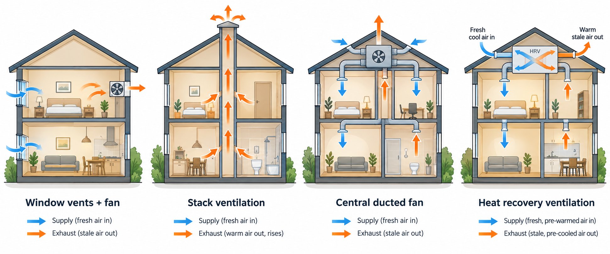
Knowing that a building must be ventilated is only half the picture. The more practical question is: how should it be ventilated? Approved Document F Volume 1 answers this by defining four distinct whole-house ventilation strategies, labeled System 1 through System 4. Each takes a fundamentally different approach to moving air, and the right choice depends on how airtight your building is, what your budget allows, and how much energy performance matters to your project.
Understanding these four systems is essential because UK building regulations part f ventilation compliance begins with selecting an appropriate strategy. Every airflow rate, every background ventilator specification, and every commissioning requirement that follows is tied to which system you choose. Let's walk through each one.
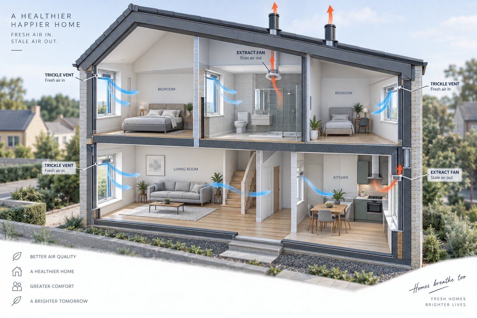
This is the most familiar setup in UK dwellings and remains the default for many standard homes, refurbishments, and window replacement projects. Picture your typical house: trickle vents built into the window frames allow a steady trickle of outdoor air into habitable rooms like bedrooms and living rooms, while extract fans in wet rooms - kitchens, bathrooms, utility rooms - pull moisture-laden and polluted air out when triggered manually by a switch or automatically by a humidity sensor.
The beauty of System 1 is its simplicity. There is no central mechanical unit, no ductwork network running through ceiling voids, and no commissioning of fan speeds across multiple terminals. The background ventilators require continuous air supply by providing specified equivalent areas, measured in square millimeters, that vary depending on the room type and overall dwelling size. The extract fans operate intermittently at defined boost rates - switching on during cooking or showering and off when the moisture source stops.
However, System 1 has a critical limitation. It relies on air entering the building through those background ventilators and through incidental gaps in the building fabric. In dwellings with air permeability above 5 m³/(h·m²) at 50 Pa, this works adequately. Drop below that threshold into more airtight construction, and System 1 can no longer deliver sufficient fresh air on its own. For highly airtight new builds, you'll need to look further down the list.
Imagine warm air rising through a chimney - that is essentially how passive stack ventilation works, minus the fireplace. Vertical ducts run from wet rooms up through the building to outlets at or above roof ridge level. Warm, moisture-laden air naturally rises through these ducts due to thermal buoyancy, creating a gentle extraction effect. Cooler outdoor air replaces it by entering through background ventilators installed in habitable rooms, just as with System 1.
Wind effects across the roof outlet enhance the draw using the Venturi principle, and humidity-sensitive outlets can be fitted to increase airflow during peak moisture events like showering.
The main advantage? In its simplest form, passive stack ventilation requires no electrical energy to operate. There are no fans running, no electricity costs, and no mechanical components to maintain.
The disadvantages are equally clear. Performance depends heavily on external conditions - wind speed, temperature differential between inside and outside - which means the system can under-ventilate on still, warm days and over-ventilate during cold, windy weather. It also requires space for ducting routes from wet rooms to roof level, which can complicate layouts in multi-story dwellings. For these reasons, passive stack ventilation is rarely specified in modern new builds, though it occasionally appears in low-energy retrofit designs where simplicity is valued over precision.
Step up from intermittent fans to something that never switches off. Continuous mechanical extract ventilation, commonly called MEV, uses either a single centralized fan unit or decentralized individual fans (dMEV) in each wet room to extract air from the building at a low, continuous trickle rate. When you cook or shower, the system boosts to a higher extraction rate before returning to its baseline.
Here is a detail that catches people out: MEV systems still require background ventilators for air supply. The fans pull air out, but fresh air must enter in through trickle vents or wall-mounted ventilators in habitable rooms. Without these supply paths, the system creates negative pressure that can cause discomfort, noise through gaps, and even backdrafting of flues.
MEV is suitable for dwellings at any airtightness level, but it really comes into its own in highly airtight buildings where System 1 falls short. The continuous low-rate extraction ensures that ventilation needs are met around the clock, not just when an occupant remembers to flick a switch. This reliability, combined with moderate installation complexity and reasonable cost, has made MEV - particularly decentralized dMEV - the most widely installed system in volume new-build housing across England.
One trade-off to consider: because MEV extracts warm indoor air and replaces it with unheated outdoor air entering through passive vents, heat is lost in the process. The system ventilates effectively but does nothing to recover that thermal energy.
This is where ventilation and energy efficiency converge. MVHR is a balanced system - it simultaneously extracts stale air from wet rooms and supplies filtered fresh air to habitable rooms, all through a dedicated ductwork network. The magic happens inside a central heat exchanger unit, typically mounted in a utility cupboard or loft space, where outgoing warm air transfers its heat to the incoming cold air stream without the two airflows mixing.
Modern MVHR units recover between 73% and 92% of the heat from extracted air, depending on the unit quality and installation. For Part F compliance, a minimum heat recovery efficiency of around 73% is expected, though quality units routinely achieve 85% to 92%.
A key distinction from every other system: MVHR typically does not require additional background ventilators. Because the unit provides its own mechanically driven supply air, there is no need for trickle vents or wall vents to let outdoor air seep in passively. This makes MVHR the natural partner for highly airtight buildings - Passivhaus projects, premium new builds, and developments targeting strong EPC ratings under Part L.
The downsides are real, though. Capital cost is significantly higher than any other system. Installation is complex, requiring careful ductwork design, airtight connections, and professional commissioning. Filters need replacing every 6 to 12 months. And MVHR performs best in very airtight dwellings; in a leaky building, the system works against itself as uncontrolled air bypasses the heat exchanger entirely, negating much of the energy benefit.
Choosing between these systems means weighing airtightness, budget, building type, and energy targets against one another. The comparison below distills the key differences into a single reference.
| Criteria | System 1: Background Ventilators + Intermittent Extract | System 2: Passive Stack | System 3: MEV / dMEV | System 4: MVHR |
|---|---|---|---|---|
| Background Ventilation Needed | Yes - trickle vents or wall vents in habitable rooms | Yes - trickle vents or wall vents in habitable rooms | Yes - trickle vents or wall vents for supply air | No - supply air provided mechanically |
| Typical Application | Standard dwellings, refurbishments, window replacements | Low-energy retrofits, simple dwellings | Volume new-build housing, flats, airtight dwellings | High-spec new builds, Passivhaus, premium developments |
| Energy Efficiency Rating | Low - no heat recovery, relies on passive air entry | Low - no heat recovery, variable performance | Moderate - continuous extraction but no heat recovery | High - recovers 73-92% of heat from exhaust air |
| Suitable Building Airtightness | Above 5 m³/(h·m²) at 50 Pa | Above 5 m³/(h·m²) at 50 Pa | Any level, especially effective below 5 m³/(h·m²) | Any level; most effective below 3 m³/(h·m²) |
| Commissioning Required | No | No | Yes - mandatory under 2021 edition | Yes - mandatory under 2021 edition |
| Installation Complexity | Low | Low to moderate | Medium | High |
One pattern emerges clearly from this comparison: the tighter the building, the more mechanical intervention is needed. Systems 1 and 2 work in leakier constructions where incidental infiltration supplements the designed ventilation. Systems 3 and 4 take over where that infiltration disappears - and System 4 goes further by turning ventilation from an energy cost into a partial energy recovery mechanism.
Each of these systems, however, is only as good as the specific airflow rates it delivers to each room. A correctly chosen system installed with undersized fans or inadequate background ventilator areas will still fail building control inspection. That brings us to the numbers themselves - the minimum litres per second and CFM values that define what "adequate ventilation" actually looks like in a kitchen, a bathroom, a bedroom, and every other occupied space.
Selecting the right ventilation system is only the first decision. The follow-up question is immediate and practical: how much air does each room actually need? Every kitchen, bathroom, utility room, and habitable space has a defined minimum airflow rate that your chosen system must deliver. Miss these numbers, and your installation will fail building control inspection regardless of how well the ductwork is routed or how premium the hardware looks.
This is where building regulations ventilation requirements get specific. The tables below translate regulatory text into room-by-room figures you can reference during design, specification, and commissioning.
Under Approved Document F Volume 1, extract ventilation rates depend on both the room type and the ventilation system installed. Systems 1 and 2 use intermittent extract - fans that switch on during moisture-producing activities and off when the task is done. Systems 3 and 4 operate continuously at a lower baseline rate with a boost mode for peak demand. The intermittent rates published in ADF guidance are as follows:
| Room Type | System 1 & 2: Intermittent Boost Rate | System 3 & 4: Continuous Minimum Rate | System 3 & 4: Intermittent Boost Rate |
|---|---|---|---|
| Kitchen (cooker hood) | 30 l/s | 13 l/s | 30 l/s (adjacent to hob) |
| Kitchen (other extract fan) | 60 l/s | 13 l/s | 60 l/s (elsewhere in kitchen) |
| Utility Room | 30 l/s | 8 l/s | 30 l/s |
| Bathroom (with or without WC) | 15 l/s | 8 l/s | 15 l/s |
| Sanitary Accommodation (WC only) | 6 l/s | 6 l/s | 6 l/s |
Notice the dramatic difference in kitchen rates. A cooker hood positioned directly above the hob captures steam and cooking fumes at source, so it only needs half the airflow of a wall- or ceiling-mounted fan located elsewhere in the room. That 30 l/s versus 60 l/s distinction is one of the most commonly misunderstood details in domestic ventilation design.
For Systems 3 and 4, the continuous minimum rate represents the baseline airflow that runs around the clock to maintain general indoor air quality. The boost rate kicks in during cooking, bathing, or other moisture-generating activities. Designing to only the boost rate while ignoring the continuous minimum - or vice versa - will leave the system non-compliant.
Purge ventilation sits alongside these extract rates as an additional requirement. Every habitable room must have a means of rapid air exchange, typically an openable window. As Approved Document F specifies, the openable area must be at least 1/20th of the room's floor area when the opening angle exceeds 30 degrees. For a bedroom measuring 14 m², that translates to a minimum openable window area of 0.7 m². Purge ventilation is your emergency flush - designed for scenarios like post-decoration paint fumes, a smoke event, or rapid moisture clearance after a long shower.
The US approach to ventilation rates works fundamentally differently from the UK model. Rather than assigning a fixed litres-per-second value to each room type, ASHRAE Standard 62.1 uses a Ventilation Rate Procedure that combines two components for commercial and institutional buildings:
CFM - cubic feet per minute - is the standard unit for measuring airflow volume in US mechanical systems. In simple terms, the cfm mechanical meaning refers to how many cubic feet of air pass through a duct, fan, or ventilation opening every minute. One CFM equals approximately 0.47 litres per second, so you can mentally halve a CFM figure to get a rough l/s equivalent.
The total outdoor airflow for any zone is the sum of these two components, adjusted by the zone air distribution effectiveness factor. The table below shows representative rates from ASHRAE 62.1 for common commercial space types:
| Space Type | Default Occupancy Density (people per 1,000 ft²) | Outdoor Air Rate per Person (CFM/person) | Outdoor Air Rate per Area (CFM/ft²) |
|---|---|---|---|
| Office Space | 5 | 5 | 0.06 |
| Classroom (ages 9+) | 35 | 10 | 0.12 |
| Retail (sales floor) | 15 | 7.5 | 0.12 |
| Hotel/Motel Guest Room | See note below | 5 | 0.06 |
| Restaurant Dining Area | 70 | 7.5 | 0.18 |
Let's put these numbers in context. For a 5,000 ft² office, you would calculate 25 occupants (5 per 1,000 ft²) times 5 CFM per person, plus 5,000 ft² times 0.06 CFM/ft², yielding a total outdoor air requirement of 425 CFM. The same logic applies to every space type in the table, though the dramatically different occupancy densities and per-person rates reflect the varying metabolic loads and pollutant profiles of each environment.
Hotel guest rooms deserve special attention because practitioners frequently search for the ASHRAE 62.1 hotel motel guest room ventilation rate cfm/person cfm/ft2. Guest rooms use the same additive formula - a per-person component plus a per-area component - but the assumed occupancy is typically based on the room's intended sleeping capacity rather than a density per thousand square feet. At 5 CFM per person and 0.06 CFM/ft², even a modest 300 ft² guest room requires meaningful outdoor air delivery. Many designers working with the ASHRAE 62.1 air changes per hour lodging guest room minimum find it helpful to convert the calculated CFM total into an air changes per hour (ACH) equivalent by dividing the volumetric airflow by the room volume - a useful cross-check, though ASHRAE 62.1 itself prescribes rates in CFM rather than ACH.
For residential buildings, ASHRAE Standard 62.2 takes a simpler approach. Whole-building mechanical ventilation is calculated using a formula based on the dwelling's floor area and number of bedrooms. Local exhaust requirements mandate intermittent or continuous extraction in kitchens (typically 100 CFM intermittent or 25 CFM continuous) and bathrooms (50 CFM intermittent or 20 CFM continuous). These figures parallel the UK's System 1 and System 3 approaches, though the specific values differ.
Extract rates handle the outgoing air, but what about the incoming supply? For UK dwellings using Systems 1, 2, or 3, outdoor air enters through background ventilators - most commonly trickle vents integrated into window frames. Approved Document F specifies minimum equivalent areas for these ventilators, measured in square millimeters (mm²), and the values vary by room type and dwelling size.
Equivalent area is not simply the physical opening size. It is a measured performance value that accounts for the aerodynamic resistance of the ventilator, tested under standardized conditions. A ventilator with a large slot but high internal resistance may have a lower equivalent area than a smaller, more aerodynamically efficient design.
As a general framework, the requirements work like this:
The exact equivalent area values are set out in tables within Approved Document F Volume 1 and vary between the four systems. System 4 (MVHR) is the exception - because supply air is delivered mechanically, additional background ventilators are generally not required, and fitting them can actually undermine system performance by allowing uncontrolled air to bypass the heat exchanger.
For practitioners, the critical takeaway is this: when specifying replacement windows or designing a System 1 installation, you must match the background ventilator equivalent area to the values required for that specific room and dwelling size. An undersized trickle vent that looks compliant on the surface but delivers insufficient equivalent area is one of the most common reasons ventilation installations fail inspection - a pattern of failures worth examining in detail alongside the other pitfalls that trip up even experienced contractors.
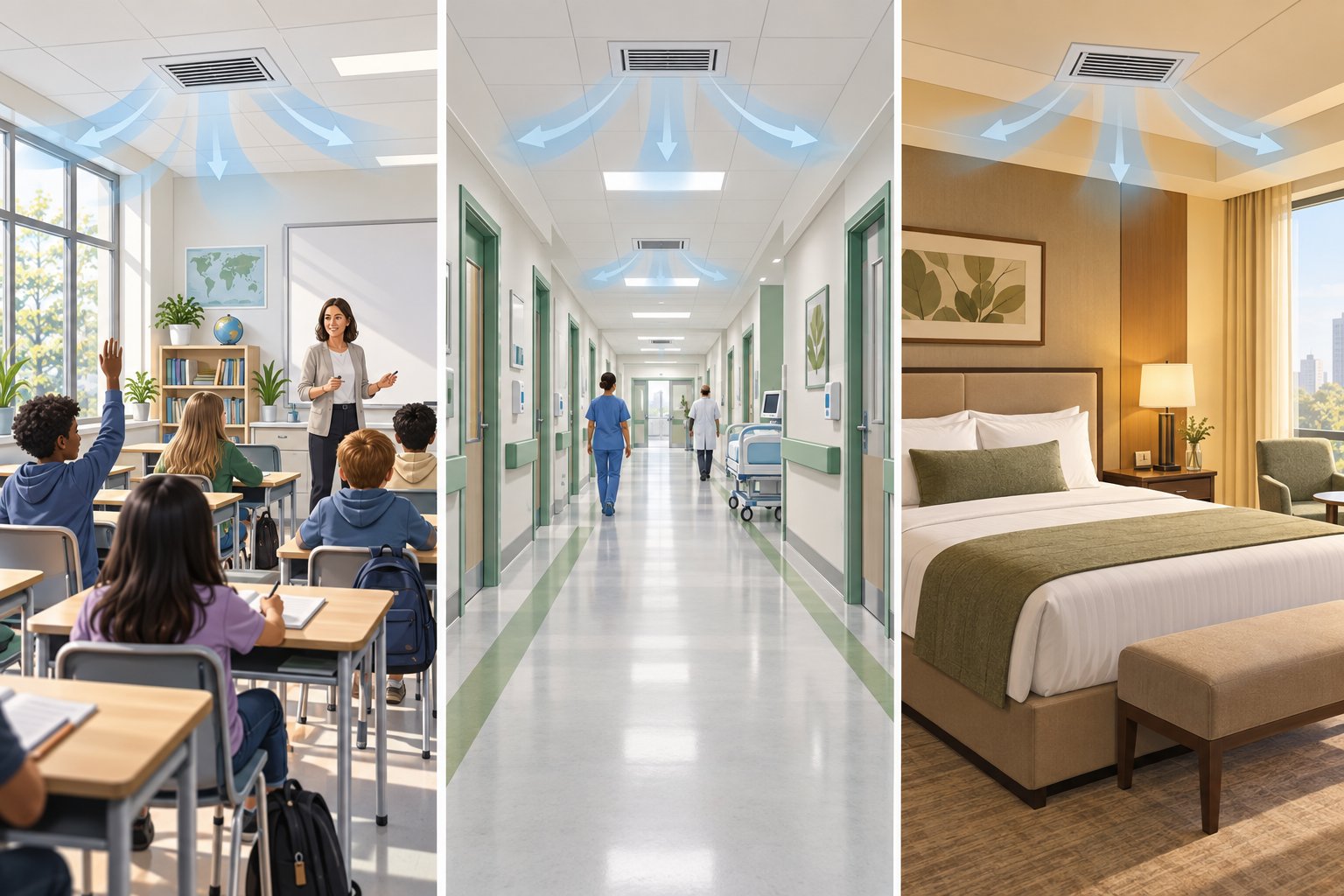
Residential airflow tables cover a large share of everyday projects, but they tell you nothing about the office block, the school classroom, or the hospital ward where the stakes - and the occupant densities - are fundamentally different. Fresh air requirements for commercial buildings, educational facilities, and healthcare environments follow their own regulatory logic, and practitioners who work across these sectors need to understand how the rules shift from one building type to the next.
For offices and retail, the governing documents are Approved Document F Volume 2 in England and ASHRAE 62.1 in the US. Both frameworks base their ventilation calculations on three variables: how many people occupy the space, what activities happen there, and what pollutant sources are present beyond human bioeffluents.
The key difference from residential design? You are no longer assigning a fixed extraction rate to a room label like "kitchen" or "bathroom." Instead, outdoor air rates are calculated using the Ventilation Rate Procedure - the additive formula combining a per-person rate with a per-area rate described in the previous section. A 10,000 ft² retail floor with an assumed density of 15 people per 1,000 ft² needs dramatically more outdoor air than a 5,000 ft² office at 5 people per 1,000 ft², even if the buildings sit side by side on the same street.
In the UK, Volume 2 provides benchmark outdoor air supply rates for common non-domestic spaces and permits designers to use either prescribed rates or a detailed calculation approach. Mechanical supply-and-extract systems dominate commercial buildings because natural ventilation alone rarely delivers the consistent airflow control needed across large, deep-plan floor plates.
Classrooms are among the most demanding spaces to ventilate properly. Pack 30 children into a room designed for quiet study, and CO2 levels can climb past 1,500 ppm within an hour if the ventilation system falls short. High occupancy density is the driving factor - ASHRAE 62.1 assigns classrooms an occupancy density of 35 people per 1,000 ft² combined with a per-person outdoor air rate of 10 CFM, nearly double the office rate.
In the UK, school ventilation goes beyond Approved Document F. The Department for Education publishes Building Bulletin 101 (BB 101), a dedicated guidance document covering ventilation, thermal comfort, and indoor air quality in school buildings. BB 101 is used to satisfy Section 1 of Approved Document F specifically for schools, providing performance criteria and spreadsheet calculation tools tailored to classroom environments. It sets minimum outdoor air supply rates, maximum CO2 concentration thresholds, and overheating limits that general-purpose ventilation guidance does not address with the same granularity.
CO2 monitoring has become a central proxy for ventilation adequacy in schools, particularly since the pandemic-era push to improve classroom air quality. Real-time CO2 sensors give teachers and facilities managers visible evidence of whether fresh air delivery keeps pace with occupancy - a far more intuitive feedback mechanism than checking fan speed settings or trickle vent positions.
Healthcare and hospitality may seem like an unlikely pairing, but they share one characteristic: both have ventilation requirements that go well beyond standard commercial benchmarks, driven by infection control on one side and guest comfort on the other.
In healthcare, ventilation is not just about air quality - it is a clinical tool. Pressure hierarchies between adjacent rooms prevent airborne contaminants from migrating into clean zones. Operating rooms are maintained at positive pressure relative to corridors, while airborne infection isolation (AII) rooms operate under negative pressure to contain pathogens. The governing standard in the US is ANSI/ASHRAE/ASHE Standard 170, Ventilation of Health Care Facilities, which specifies minimum total air changes per hour, outdoor air changes per hour, pressure relationships, and filtration requirements for every clinical space type. Standard 170 was adopted into the International Mechanical Code beginning with the 2015 edition, and it also forms part of the NFPA 99 Health Care Facilities Code - relevant for practitioners asking which NFPA standard deals with air conditioning and ventilating systems in medical settings.
The 2021 edition of Standard 170 introduced significant changes, including unoccupied turndown provisions that allow reduced airflow when rooms are empty, updated filtration requirements elevating operating rooms to MERV 16, and post-pandemic guidance permitting AII room exhaust to combine with general exhaust when HEPA-filtered. In the UK, healthcare ventilation follows HTM 03-01 (Specialised ventilation for healthcare premises), which similarly mandates air change rates, pressure cascades, and filtration standards calibrated to clinical risk.
Hospitality presents a different challenge. Hotel guest rooms need enough outdoor air for sleeping comfort without drafts or excessive noise. Under ASHRAE 62.1, the ASHRAE 62.1 hotel guestroom air changes per hour minimum is derived from a per-person rate of 5 CFM plus a per-area rate of 0.06 CFM/ft², as outlined in the previous section's rate tables. Meeting OSHA ventilation standards for workplace areas within hotels - kitchens, laundry facilities, maintenance workshops - adds another layer, as these operational zones have elevated pollutant loads that demand higher extraction rates than guest corridors or lobbies.
Smoke ventilation also intersects with these building types. In the UK, smoke vent regulations uk requirements under Approved Document B (fire safety) may mandate dedicated smoke exhaust systems in corridors, atriums, and basement areas of healthcare and hospitality buildings. These smoke ventilation provisions operate independently of the day-to-day fresh air systems governed by Part F, but the ductwork routes and shaft space must be coordinated during design to avoid conflicts.
What connects every building type in this section is a shared principle: the more vulnerable the occupants or the more concentrated their numbers, the more deliberate and robust the ventilation strategy must be. A classroom full of children, an operating theater, and a hotel guest room each demand purpose-designed airflow - and each penalizes under-ventilation in different but equally consequential ways. The tightest modern envelopes only amplify these demands, creating a paradox that sits at the heart of contemporary building design.

Picture a house built in the 1970s. Gaps around window frames, poorly sealed loft hatches, air leaking through floorboards - these "defects" actually served a hidden purpose. Draughty construction provided incidental ventilation, pulling fresh outdoor air through the building fabric without anyone designing a system to do it. Indoor air quality was rarely ideal, but the risk of stale, moisture-laden air building up to dangerous levels stayed relatively low because the building itself was a sieve.
Fast-forward to a modern dwelling designed to meet current energy efficiency targets, and the picture flips entirely. Walls are insulated to within millimeters of their thermal limit. Windows are triple-glazed. Membranes and tapes seal every junction. The result? A building envelope so tight that those incidental air pathways vanish - and with them, the free ventilation that older buildings took for granted.
This is the paradox at the core of contemporary building regulations ventilation requirements: the better a building performs thermally, the worse it performs in terms of natural air exchange. Solving one regulatory problem creates another unless both are addressed together from the start.
Approved Document F assumes a design air permeability of 5 m³/(h·m²) at 50 Pa for new homes - a threshold that represents a moderately airtight envelope. Many contemporary builds go significantly further, targeting values of 3 m³/(h·m²) or below to satisfy Part L energy conservation targets in the UK or IECC mandates in the US. Passivhaus-certified dwellings push airtightness to 0.6 air changes per hour at 50 Pa - a level where virtually no air enters or exits the building unless you design a deliberate pathway for it.
Why does this matter practically? Because the outside air ventilation that occupants depend on for health - diluting CO2, flushing out moisture from cooking and showering, dispersing volatile organic compounds off-gassing from furniture and finishes - simply cannot happen through a building fabric that permits almost zero uncontrolled infiltration. Without a designed ventilation strategy, moisture accumulates on cold surfaces, mold colonizes walls, and CO2 concentrations climb to levels that cause headaches, fatigue, and impaired cognitive function. The term for this cluster of symptoms is sick building syndrome, and airtight buildings without adequate ventilation are particularly susceptible.
This regulatory interdependency means Part F and Part L compliance must be considered simultaneously, not in sequence. An architect who designs the thermal envelope to pass Part L without a coordinated ventilation strategy risks failing Part F - and a building that achieves excellent energy ratings on paper but makes its occupants ill in practice. The same principle applies in US jurisdictions where IECC-driven envelope tightness must be reconciled with HVAC fresh air intake requirements under the IMC and ASHRAE standards.
Imagine you could ventilate your home with fresh, filtered air around the clock while recovering most of the heat you have already paid to generate. That is exactly what mechanical ventilation with heat recovery delivers, and it is the reason MVHR has become the default ventilation strategy for high-performance buildings where both ventilation and energy codes apply at their most demanding levels.
An MVHR unit extracts stale, warm air from wet rooms - kitchens, bathrooms, utility spaces - and passes it through a heat exchanger where its thermal energy transfers to the incoming stream of cold outdoor air. The two airflows never mix. The outgoing air surrenders its heat and exits the building; the incoming air arrives pre-warmed and filtered, ready to supply habitable rooms. Modern units routinely achieve heat recovery efficiencies of 73% to over 90%, with the updated Approved Document F setting a minimum threshold of 73%. Commercial-grade systems specified in office and institutional buildings can capture up to 90% of thermal energy from exhaust air, drastically reducing heating coil loads while maintaining continuous fresh air requirements for HVAC compliance.
The dual benefit is what makes MVHR uniquely positioned at the intersection of ventilation and energy regulation:
There is an important caveat, though. MVHR performs best - and is most cost-effective - in dwellings with air permeability below approximately 3 m³/(h·m²) at 50 Pa. In a leaky building, uncontrolled air bypasses the heat exchanger entirely, entering through gaps in the fabric that the system cannot capture or condition. You end up paying for a premium ventilation unit while cold draughts still whistle through poorly sealed junctions. The energy recovery benefit evaporates, and the system becomes an expensive extract fan.
This is why the Part L 2025/2026 update in the UK pushes a "fabric first" approach - get the envelope right before specifying the mechanical systems. An MVHR unit paired with a genuinely airtight envelope is a powerful combination. The same unit bolted onto a building with unsealed penetrations and poorly fitted windows is a waste of money and a compliance headache.
Not every project needs or can afford a full MVHR installation. For moderately airtight dwellings - those sitting in the 3 to 5 m³/(h·m²) range - passive and semi-passive ventilation strategies can still meet fresh air requirements for HVAC-lean designs without the capital cost, ductwork complexity, or ongoing filter maintenance that MVHR demands.
The workhorse of passive ventilation in these buildings is the background ventilator - most commonly a trickle vent integrated into the window frame. Trickle vents provide a controlled, permanent opening with a defined equivalent area (measured in mm²) that allows outside air to enter habitable rooms at a steady, low-level rate. When paired with intermittent extract fans in wet rooms (System 1) or continuous mechanical extract (System 3), trickle vents form the supply side of the ventilation equation.
The design challenge is precision. A trickle vent with too large an equivalent area in a cold climate creates uncomfortable cold draughts and wastes heating energy - effectively punching a hole in the thermal envelope you worked so hard to seal. Too small, and the room does not receive enough fresh air to meet regulatory minimums. Research conducted in controlled climate chamber conditions confirms that airflow through trickle vents is directly proportional to the indoor-outdoor pressure difference, meaning vent performance varies with wind exposure, building height, and seasonal temperature differentials. On upper floors of multistory buildings, where natural stack-effect pressures diminish, a single vent may deliver significantly less airflow than the same unit installed at ground level.
Acoustic performance adds another layer. In noise-sensitive locations near busy roads or airports, standard slot-type ventilators may allow excessive noise ingress even while providing adequate airflow. Acoustically attenuated trickle vents address this by incorporating baffles or labyrinthine air paths that reduce sound transmission while maintaining the required equivalent area - a balance that demands careful product selection rather than defaulting to the cheapest off-the-shelf option.
For buildings in the moderately airtight range, the practical recipe looks like this: seal the envelope well enough to control heat loss, install properly sized background ventilators to deliver the equivalent areas specified in Approved Document F for each room, and pair them with either intermittent or continuous extract to create a functioning ventilation pathway. It is a simpler, more affordable route than MVHR, and for the right building, it works. The critical step is matching the ventilation strategy to the actual airtightness achieved - a decision that changes fundamentally depending on whether the project is a new build designed from scratch or a renovation where existing fabric constrains what is possible.
A brand-new dwelling designed from a blank sheet and a 1930s terrace getting replacement windows are worlds apart in construction complexity - yet both must satisfy the same underlying regulation ventilation principle: the building must not be left with inadequate fresh air. What differs dramatically is the scope of compliance, the system options available, and the practical steps needed to pass building control inspection.
This distinction trips up more professionals than almost any other aspect of Part F building regulations. A new build demands a holistic ventilation strategy baked into the design from day one. A window replacement only needs to prove that ventilation has not been made worse. An extension sits somewhere in between. And a loft conversion? That triggers a compliance standard closer to a new build than most homeowners expect. Let's break each scenario down.
Every new dwelling must achieve full compliance with the current edition of Approved Document F Volume 1. There is no partial credit and no grandfather clause - the ventilation strategy must meet today's standards in their entirety.
In practice, this means the ventilation design is not an afterthought bolted on once the walls are up. It is developed alongside the building fabric specification and submitted as part of the building control application. The design team selects one of the four ventilation systems covered earlier in this article - System 1 through System 4 - and that choice cascades into every subsequent decision: background ventilator equivalent areas, extract fan sizes, ductwork routes, and commissioning requirements.
For a new-build dwelling targeting moderate airtightness (around 5 m³/(h·m²) at 50 Pa), System 1 or System 3 is typically the most straightforward path. For highly airtight construction below 3 m³/(h·m²), System 4 (MVHR) becomes the natural choice because passive air supply through background ventilators alone cannot reliably meet the ventilation required for healthy indoor air quality.
Key obligations for new builds include:
In the US, the equivalent new-construction pathway requires designers to satisfy the applicable state-adopted code - whether that references ASHRAE 62.2 for residential buildings or the IMC for mechanical system design. The principle mirrors the UK approach: design the ventilation system as an integral part of the building, not a last-minute addition.
Here is where compliance catches the most people off guard. You are not building a new house. You are simply fitting new windows in an existing property. Surely ventilation regulations do not apply?
They absolutely do. Under Part F building regulations, when you replace windows in an existing dwelling, the ventilation provision must be no worse than before the work was carried out. This is codified in Regulation 4(3) of the Building Regulations 2010, and the government's own FAQ on Approved Document F Volume 1 makes the position unambiguous: a homeowner cannot sign a disclaimer opting out of background ventilation, nor can an indemnity policy substitute for meeting the requirements in full.
What does this mean in practical terms? If the original windows had trickle vents, the replacement windows must include trickle vents providing at least the same equivalent area. If the originals did not have trickle vents - common in older properties - but the dwelling relies on System 1 ventilation (background ventilators plus intermittent extract), the replacement windows should be fitted with background ventilators to meet the minimum equivalent areas described in Approved Document F Volume 1.
There is one exception worth noting. If an existing wall ventilator already installed in the room meets the minimum equivalent area requirements, no further background ventilation needs to be added after replacing the windows. However, air vents serving open-flued combustion appliances (installed to meet Part J requirements) do not count toward Part F background ventilation - they serve a different regulatory purpose.
Another common misconception involves night-latch positions. A window locked slightly ajar on a night-vent setting is not an acceptable substitute for a trickle vent. As the government FAQ explicitly states, windows on the night-latch do not provide a sufficiently secure means of background ventilation. The solution must be a dedicated, controllable background ventilator integrated into or adjacent to the window frame.
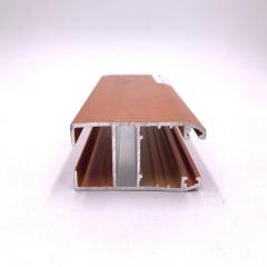
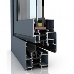
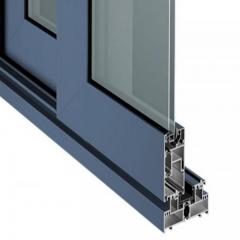
This is precisely where frame-ready trickle vent products become essential for straightforward compliance. Products like Shengxin Aluminium's Window Trickle Vents, designed for integration into both aluminium and uPVC window frames, give architects and window manufacturers a practical way to meet equivalent area requirements without redesigning the fenestration. For noise-sensitive locations near busy roads, acoustically rated trickle vents that incorporate sound-attenuating design while maintaining compliant airflow are recommended under paragraph 1.54 of Approved Document F Volume 1 - making acoustic performance a key specification criterion alongside equivalent area data.
Members of Competent Person Schemes who self-certify window installations must confirm that all relevant Building Regulations requirements have been met, including ventilation. Non-compliant work can trigger enforcement action, and scheme operators are obligated to monitor their registrants and act against anyone certifying work that fails to comply.
Extensions follow a slightly different rule. Any new rooms added to an existing dwelling must meet current ventilation standards in full - the same rates, same system options, and same background ventilator equivalent areas as a new build. However, the existing rooms in the original dwelling are not required to be upgraded to current standards unless the extension work materially affects their ventilation. In practical terms, this means a new kitchen extension needs compliant extract and background ventilation from day one, while the existing living room on the other side of the wall stays as it is - provided you have not blocked or removed any of its original ventilation pathways.
Converting a space that was never intended for habitation into a dwelling - or part of a dwelling - triggers a compliance threshold that surprises many project owners. A loft conversion, a garage-to-bedroom conversion, or a commercial-to-residential change of use all fall under what the Building Regulations call a material change of use, and the ventilation requirements for the converted areas mirror those of a new build.
Imagine converting a dusty, unoccupied loft into a bedroom with an en-suite bathroom. That new bedroom needs background ventilators meeting the equivalent area specified for a habitable room of its size and dwelling configuration. The en-suite needs an extract fan delivering the minimum intermittent or continuous rate for a bathroom - 15 l/s intermittent or 8 l/s continuous, depending on the chosen system. Purge ventilation via an openable roof window (such as a Velux or dormer) must achieve at least 1/20th of the room's floor area. If the conversion creates an airtight space within the roof structure, a mechanical ventilation strategy - potentially including MVHR - may be the only viable route to compliance.
Loft conversions also intersect with multiple other Approved Documents beyond Part F. Structural safety under Part A, fire safety under Part B (including escape routes and fire-rated doors), energy efficiency under Part L, and electrical safety under Part P all apply simultaneously. Building control officers inspect the conversion at critical stages - during framing, after insulation, and at completion - and a Completion Certificate is only issued once every applicable requirement is satisfied, ventilation included.
Commercial-to-residential conversions present the same regulatory trigger but with added complexity. A former office or retail unit being converted into flats must meet Approved Document F Volume 1 for each individual dwelling created, even though the original space may have been ventilated under the entirely different provisions of Volume 2. The ventilation strategy effectively starts from scratch for the residential portions, while any remaining commercial areas continue to follow the non-domestic guidance.
Across all of these scenarios - new builds, window replacements, extensions, and conversions - a single thread runs through the compliance process: evidence. Building control expects documented proof that the ventilation strategy was designed to meet the required rates, that the products installed deliver the specified performance, and that mechanical systems were commissioned and balanced. That documentation trail, and the common points where it breaks down, is where many otherwise solid installations stumble on their way to sign-off.
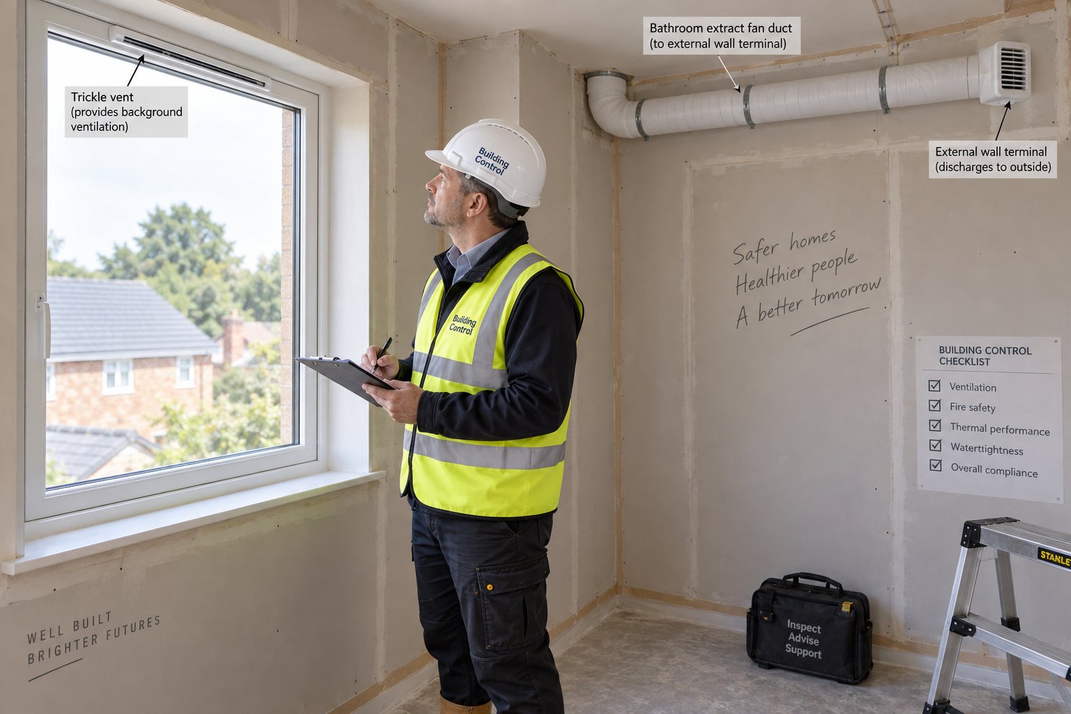
Designing a ventilation strategy on paper is one thing. Getting it past a building control officer on inspection day is something else entirely. Even experienced contractors and specifiers trip over the same handful of mistakes - errors that look minor during installation but become deal-breakers at sign-off. Understanding what goes wrong, and why, saves you the cost and delay of rework far more effectively than memorizing airflow tables.
The failures listed below are drawn from patterns that building control officers encounter repeatedly across both residential and commercial projects. Every one of them is avoidable with forethought.
When a building control officer walks through your project at final inspection, they are not guessing. They follow a structured checklist, and they expect specific evidence at each stage. Here is what you should have ready:
A route that can simplify this process is self-certification through Competent Person Schemes. Registered installers belonging to schemes such as BESCA, Certsure, or NAPIT can self-certify mechanical ventilation and air-conditioning installations in dwellings and other buildings without a separate building control inspection. The scheme operator notifies the local authority on the installer's behalf, and a compliance certificate is issued directly. This pathway works well for straightforward installations, but the installer remains fully responsible for ensuring the work meets all applicable ventilation codes - including correct sizing, commissioning, and documentation.
In the US, the inspection process varies by jurisdiction but follows a parallel logic. Local code officials check installed systems against the requirements of whichever edition of the International Mechanical Code has been adopted locally - whether that is the 2015 IMC, the 2021 International Mechanical Code, or a later edition. Projects governed by the International Mechanical Code 2015 should be especially careful to verify which ventilation rate tables and ductwork standards apply, since subsequent editions introduced revised outdoor air calculations and updated references to ASHRAE 62.1. Confirming the locally enforced IMC edition before design begins prevents costly specification errors that only surface at inspection.
If you are navigating building regulations ventilation requirements for the first time - whether as a self-builder, a new contractor, or an architect specifying your first domestic project - these practical steps will help you avoid the failures above and reach sign-off without unnecessary delays:
The thread connecting every one of these tips is timing. Ventilation compliance is not a box you tick at the end of a build. It is a series of decisions that start at concept design and accumulate evidence throughout construction. Get the sequence right, and sign-off becomes a formality. Get it wrong, and you are retrofitting trickle vents into sealed window frames or rerouting ductwork through finished ceilings - neither of which is cheap, fast, or pleasant.
With these pitfalls mapped and the inspection process demystified, the remaining question is strategic: given everything covered so far, how do you choose the right ventilation approach for your specific project and source the components that make compliance straightforward rather than stressful?
Every room-by-room rate, every system comparison, and every compliance failure discussed throughout this article converges on one practical question: what do you actually do next? The answer depends on your role, your project type, and the airtightness level you are targeting. Rather than rehashing what each regulation says, this final section distills the guidance into decision-ready steps for architects, window manufacturers, contractors, and specifiers.
Think of ventilation strategy selection as a funnel. Three variables narrow your options quickly: building airtightness, project scope, and budget.
For standard dwellings with moderate airtightness - air permeability in the range of 5 to 8 m³/(h·m²) at 50 Pa - System 1 (background ventilators paired with intermittent extract fans) remains the most cost-effective and widely used approach. It requires no ductwork network, no centralized unit, and no ongoing filter maintenance. The critical compliance step is ensuring that every habitable room has background ventilators meeting the equivalent area values specified in Approved Document F, and that every wet room has an extract fan delivering the minimum litres-per-second boost rate for its type.
For highly airtight new builds targeting strong energy performance - air permeability below 3 m³/(h·m²) at 50 Pa - System 4 (MVHR) delivers dual compliance with both ventilation and energy regulations. It recovers 73% to over 90% of heat from extracted air, eliminates the need for passive background ventilators, and provides filtered supply air to every habitable room. The trade-off is higher capital cost, dedicated duct space, and mandatory commissioning. Under the Future Homes Standard, where the notional dwelling assumes an airtightness of 4 m³/(h·m²) at 50 Pa, mechanical ventilation - whether decentralized MEV or full MVHR - is no longer optional.
For refurbishments, window replacements, and extensions, the compliance question is simpler but no less important: has the work maintained or improved the ventilation provision that existed before? In the vast majority of cases, this means specifying properly sized trickle vents in replacement window frames and installing compliant extract fans in any new wet rooms. System 1 dominates this scenario because it integrates with existing building fabric without requiring a whole-house mechanical redesign.
US practitioners face an analogous decision tree. Residential projects governed by ASHRAE 62.2 follow a formula based on floor area and bedroom count, while commercial designs under ASHRAE 62.1 and the applicable edition of the national mechanical code - whether the 2015 International Mechanical Code, the 2021 edition, or a later revision - use the ventilation rate procedure to calculate outdoor air delivery for each occupied zone. The system choice may differ, but the logic is identical: match the ventilation strategy to the building's actual envelope performance and occupancy profile.
A well-chosen ventilation strategy fails at the last mile if the physical components do not deliver the performance the design assumes. Background ventilators, in particular, are where specification errors cause the most building control rejections - not because compliant products are unavailable, but because the wrong product gets installed in the wrong opening without anyone checking the numbers.
When evaluating trickle vents and other background ventilation products, here is what to look for:
For mechanical components - extract fans, MEV units, MVHR systems - the evaluation criteria shift toward declared airflow performance at specified static pressures, specific fan power (SFP) ratings, heat recovery efficiency percentages, and availability in the Product Characteristics Database (PCDB) used by energy modeling software. A product that is not listed in the PCDB cannot be accurately modeled in SAP or HEM calculations, potentially forcing the energy assessor to use default penalties that drag down the dwelling's predicted performance.
Building regulations are living documents. The UK's Approved Document F has already been restructured into two volumes (effective June 2022), and a 2026 edition of Approved Document F Volume 1 has been published to accompany the Future Homes Standard, with earlier editions continuing to apply to buildings subject to previous regulatory standards. The ventilation landscape is shifting - tighter airtightness benchmarks, higher expectations for mechanical systems, and more sophisticated energy modeling tools all point toward increasing rigor in how fresh air delivery is designed and verified.
In the US, the three-year code cycle means a jurisdiction that adopted the 2015 International Mechanical Code may have since moved to the 2021 or 2024 edition - or it may not have. State-level code adoption timelines vary widely, and local amendments can alter specific ventilation provisions even within a single state. The 2021 UMC remains the governing mechanical code in several western states, adding another layer of jurisdictional variation that practitioners must verify project by project.
Three habits will keep you on the right side of compliance as these frameworks evolve:
Ventilation compliance is not a one-time achievement. It is an ongoing discipline - part technical knowledge, part documentation habit, and part willingness to double-check the numbers before the building control officer does it for you. The regulations exist because indoor air quality is not negotiable. Buildings that get ventilation right protect both the people inside and the fabric around them. Buildings that get it wrong pay the price in mold, in complaints, and in costly remedial work that could have been avoided with a few extra hours of attention at the design stage.
Yes. Under Part F of the Building Regulations, replacement windows must ensure ventilation is no worse than the original installation. If the dwelling uses System 1 ventilation (background ventilators plus intermittent extract), replacement windows should include trickle vents providing at least the same equivalent area as the originals. If the originals lacked trickle vents, new background ventilators must still be fitted to meet minimum equivalent area values in Approved Document F Volume 1. A window left on a night-latch position is not an acceptable substitute. Frame-ready products like Shengxin Aluminium's Window Trickle Vents, designed for both aluminium and uPVC profiles, offer a practical route to meeting these equivalent area and acoustic performance requirements without redesigning the fenestration.
Approved Document F Volume 1 defines four whole-dwelling ventilation strategies. System 1 combines background ventilators (trickle vents) with intermittent extract fans in wet rooms and suits moderately airtight homes. System 2 uses passive stack ventilation, relying on vertical ducts and natural buoyancy to extract air without mechanical fans. System 3 is continuous mechanical extract ventilation (MEV or dMEV), running low-rate extraction around the clock with boost capability, paired with background ventilators for supply air. System 4 is mechanical ventilation with heat recovery (MVHR), a balanced supply-and-extract system that recovers 73-92% of heat from outgoing air and does not require separate background ventilators. The right choice depends on building airtightness, budget, and energy performance targets.
UK kitchen extract rates depend on both the ventilation system and the fan position. For Systems 1 and 2 using intermittent extract, a cooker hood directly above the hob requires a minimum boost rate of 30 litres per second (l/s), while an extract fan positioned elsewhere in the kitchen requires 60 l/s. For Systems 3 and 4 using continuous extraction, the baseline continuous rate is 13 l/s with the same boost rates applying during cooking. This 30 versus 60 l/s distinction based on fan placement is one of the most frequently misunderstood details in domestic ventilation design and a common source of specification errors.
ASHRAE 62.1 uses a Ventilation Rate Procedure that adds two components: a people-based rate in CFM per person (accounting for occupant-generated pollutants) and an area-based rate in CFM per square foot (accounting for material off-gassing and furnishings). For example, an office requires 5 CFM per person plus 0.06 CFM/ft2, while a classroom needs 10 CFM per person plus 0.12 CFM/ft2. The total outdoor airflow is then adjusted by a zone air distribution effectiveness factor. Hotel guest rooms follow the same additive formula at 5 CFM per person plus 0.06 CFM/ft2, with assumed occupancy based on sleeping capacity rather than a density-per-area figure.
Yes. Converting a loft, garage, or commercial space into habitable residential accommodation constitutes a material change of use under the Building Regulations. This triggers full Part F compliance for the converted areas, meaning ventilation requirements mirror those of a new-build dwelling. A new bedroom needs background ventilators meeting the specified equivalent area, any en-suite bathroom requires an extract fan delivering at least 15 l/s intermittent or 8 l/s continuous, and purge ventilation via an openable window must achieve at least 1/20th of the room floor area. Building control officers inspect at critical stages and will not issue a Completion Certificate until ventilation requirements are satisfied.



 serviço on-line
 0086 136 3563 2360
 sales@sxalu.com
 +86 136 3563 2360
 português
 English
 français
 Deutsch
 русский
 español
 العربية
 ไทย
ไทย Việt
Việt Українська