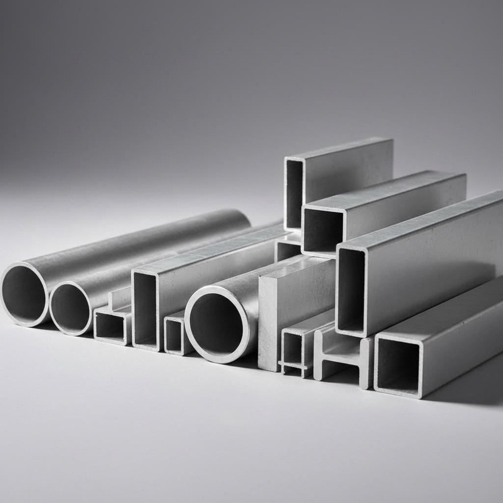
Ever received a batch of extruded aluminum profiles only to discover they don't quite fit your assembly? You're not alone. This frustrating scenario plays out in manufacturing facilities worldwide, often because engineers and designers lack a clear understanding of aluminum extrusion tolerances from the start.
So what exactly are these tolerances, and why should you care about them? Simply put, aluminum extrusion tolerances define the acceptable range of deviation from your specified dimensions during the manufacturing process. No extrusion is perfectly identical to the next. These guidelines establish the boundaries within which your parts must fall to be considered acceptable for their intended purpose.
Think of tolerances as the rulebook for precision aluminum extrusion. They tell manufacturers exactly how much variation is permissible across different dimensions of your profile. This includes everything from wall thickness and cross-sectional measurements to straightness and angular specifications.
For engineers, designers, and procurement professionals, understanding these parameters isn't optional. It's essential. Here's why tolerances matter for your projects:
According to industry experts at Paramount Extrusions, tolerances "provide the parameters within which extruders must operate to make sure that parts function as intended without requiring additional modifications." This optimization protects functionality, aesthetics, and fitment of your final product.
Here's what many aluminium extrusion design guide resources fail to explain: tolerances aren't arbitrary numbers pulled from thin air. They reflect the physical realities of the extrusion process itself. When heated aluminum billets are forced through a steel die at high pressure, countless variables influence the final dimensions.
The Aluminum Association and the American National Standards Institute (ANSI) have established standard tolerances that balance manufacturing capabilities with end-user requirements. These standards are regularly updated to reflect technological advancements in extrusion equipment and evolving industry needs.
Proper tolerance specification is the difference between a project that flows smoothly from design to delivery and one plagued by rejected parts, costly rework, and frustrating delays. Getting it right from the start saves time, money, and professional relationships.
What you'll find in this comprehensive aluminum extrusion tolerances chart resource is something no single competitor currently offers. We've combined complete reference data with practical interpretation guidance. You'll discover not just what the tolerance values are, but how to apply them intelligently to your specific applications.
Whether you're specifying tolerances for a new project or troubleshooting out-of-spec parts, this guide bridges the gap between raw technical data and real-world decision-making. Ready to stop overspecifying your designs and start optimizing your tolerance requirements? Let's dive into the standards that govern these critical specifications.
Where do tolerance values actually come from? When you're writing specifications for aluminum extrusions, you need more than rough estimates. You need authoritative reference documents that manufacturers recognize and follow. Understanding the standards behind your tolerance charts transforms you from someone guessing at numbers to a professional who speaks the industry's language.
Two primary documents form the backbone of aluminum extrusion tolerance specifications in North America. The first is ANSI H35.2-2024: American National Standard Dimensional Tolerances for Aluminum Mill Products. This incredibly technical document consists primarily of detailed tables specifying dimensional tolerances across aluminum products, including thickness, width, length, and diameter measurements.
What makes ANSI H35.2 particularly valuable? It covers aluminum in virtually all its manufactured forms. The 2024 revision includes important updates such as expanded thickness specifications in key tables and new schedule numbers for larger pipe sizes. When you download the ASTM B221 PDF or reference tolerance data, you're working with information derived from these foundational standards.
The second critical document is ASTM B221, which specifically addresses extruded wire, rod, bar, profiles, and tubes. This specification works in conjunction with ANSI H35.2 to define what manufacturers must achieve when producing your components.
Here's where many professionals get confused: The Aluminum Association develops and publishes these standards, which then become the ANSI-designated national standards. Think of The Aluminum Association as the industry body that creates the technical content, while ANSI provides the formal standardization framework.
The Aluminum Association's standards use an organized table numbering system that you'll encounter repeatedly when working with tolerance data. Familiarizing yourself with this system makes specification writing far more efficient:
For aerospace applications, additional specifications come into play. The AMS-QQ-A-225/8 specification covers 6061 aluminum alloy bar, rod, wire, and special shapes that are rolled, drawn, or cold finished. Similarly, AMS-QQ-A-200/3 addresses 2024 aluminum alloy bar, rod, shapes, tube, and wire in extruded form. These aerospace material specifications often reference tighter tolerances than standard commercial requirements.
Why does this matter for your projects? These standards provide the baseline tolerances that every reputable manufacturer works within. When you specify "standard tolerances" without further detail, suppliers interpret this according to the relevant Aluminum Association tables. When you need precision tolerances or even tighter specifications, you're asking manufacturers to exceed these baseline requirements, which typically affects cost and lead time.
Understanding that tolerance charts aren't arbitrary numbers but carefully developed industry standards changes how you approach specification writing. You're not negotiating from scratch with each supplier. Instead, you're working within a common framework that over 8 billion pounds of North American aluminum production follows annually. This shared language between designers and manufacturers eliminates confusion and ensures your parts arrive within the dimensional boundaries your application demands.
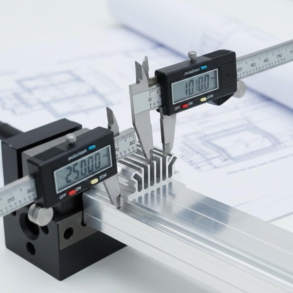
Ready to stop hunting through scattered PDFs and outdated references? This section delivers what you've been searching for: a unified aluminum extrusion tolerances chart that consolidates cross-sectional dimensions, wall thickness, straightness, twist, and angular specifications into one accessible resource. Whether you're working with standard aluminum profiles or custom aluminium extruded tubes, these tables provide the reference data you need for confident specification writing.
Cross-sectional tolerances represent the heart of aluminum extrusion dimensional control. According to The Aluminum Association's Table 11.2, tolerances vary based on profile complexity, circumscribing circle diameter, and whether dimensions measure through metal or open space. The circumscribing circle diameter refers to the smallest circle that completely encloses your profile's cross section.
Here's what this means practically: a 2-inch wide dimension through solid metal on a profile with a circumscribing circle under 10 inches carries a standard tolerance of ±0.024 inches (±0.610 mm). That same dimension measured through open space at a leg base distance of 1.250 to 2.499 inches jumps to ±0.038 inches (±0.965 mm).
| Profile Type | Specified Dimension Range | Standard Tolerance (in.) | Standard Tolerance (mm) | Precision Tolerance (in.) | Precision Tolerance (mm) |
|---|---|---|---|---|---|
| Solid Shapes - Metal Dimensions (CCD < 10 in.) | |||||
| Solid Profile | Up thru 0.124 in. | ±0.006 | ±0.152 | ±0.004 | ±0.102 |
| Solid Profile | 0.125-0.249 in. | ±0.007 | ±0.178 | ±0.005 | ±0.127 |
| Solid Profile | 0.250-0.499 in. | ±0.008 | ±0.203 | ±0.005 | ±0.127 |
| Solid Profile | 0.500-0.749 in. | ±0.009 | ±0.229 | ±0.006 | ±0.152 |
| Solid Profile | 0.750-0.999 in. | ±0.010 | ±0.254 | ±0.007 | ±0.178 |
| Solid Profile | 1.000-1.499 in. | ±0.012 | ±0.305 | ±0.008 | ±0.203 |
| Solid Profile | 1.500-1.999 in. | ±0.014 | ±0.356 | ±0.009 | ±0.229 |
| Solid Profile | 2.000-3.999 in. | ±0.024 | ±0.610 | ±0.016 | ±0.406 |
| Hollow Shapes - Wall Thickness (Enclosed Void) | |||||
| Hollow Profile | 10-15% of dimension | ±0.010 min / ±0.060 max | ±0.254 / ±1.524 | Negotiated | Negotiated |
| Semi-Hollow Shapes - Space Dimensions | |||||
| Semi-Hollow | 0.250-0.624 in. from base | ±0.010 | ±0.254 | ±0.007 | ±0.178 |
| Semi-Hollow | 0.625-1.249 in. from base | ±0.012 | ±0.305 | ±0.008 | ±0.203 |
| Semi-Hollow | 1.250-2.499 in. from base | ±0.016 | ±0.406 | ±0.011 | ±0.279 |
| Semi-Hollow | 2.500-3.999 in. from base | ±0.020 | ±0.508 | ±0.013 | ±0.330 |
For standard aluminum extrusion profiles with circumscribing circles 10 inches and over, tolerances increase significantly. A solid dimension in the 2.000-3.999 inch range carries ±0.034 inches (±0.864 mm) standard tolerance versus ±0.024 inches for smaller profiles. This reflects the greater difficulty controlling larger extrusions during the cooling and stretching processes.
Wall thickness tolerances for hollow profiles deserve special attention. According to industry reference data, wall thickness tolerance is typically expressed as 10-15% of the specified wall dimension, with minimum and maximum limits. For example, a wall specified at 0.125 inches carries a standard tolerance of approximately ±0.014 inches (±0.356 mm). When one wall is three times or greater than the opposite wall thickness, tolerances must be negotiated between purchaser and manufacturer.
Your extrusion might have perfect cross-sectional dimensions yet still fail inspection due to geometric tolerances. Straightness, twist, and angularity specifications from Tables 11.5 through 11.8 and Table 11.14 govern how your profile behaves along its length.
Straightness tolerance measures how much your extrusion can deviate from a perfectly straight line. This is calculated using a simple formula: multiply the tolerance factor by the measured length in feet. For most standard aluminum extrusions in tempers other than O (annealed), the formula works out to:
Allowable Deviation = 0.0125 × Measured Length (ft.)
What does this mean in practice? A 10-foot profile allows 0.125 inches (3.175 mm) of bow or deviation from straight. For annealed (O temper) material, tolerances increase to 0.050 × measured length, reflecting the softer material's greater susceptibility to bending.
| Geometric Property | Profile Width/CCD Range | Tolerance per Foot | Maximum Total | Practical Example (10 ft. length) |
|---|---|---|---|---|
| Straightness - All Tempers Except O, TX510, TX511 | ||||
| Rod, Bar | All sizes | 0.0125 in./ft. | — | 0.125 in. max deviation |
| Profiles | CCD up thru 1.499 in. | 0.050 in./ft. | — | 0.50 in. max deviation |
| Profiles | CCD 1.500 in. and over | 0.0125 in./ft. | — | 0.125 in. max deviation |
| Twist - All Tempers Except O, TX510, TX511 | ||||
| Bar, Profiles | Up thru 1.499 in. | 1° per ft. | 7° | 7° maximum twist |
| Bar, Profiles | 1.500-2.999 in. | 0.5° per ft. | 5° | 5° maximum twist |
| Bar, Profiles | 3.000 in. and over | 0.25° per ft. | 3° | 2.5° actual twist |
| Angularity - Standard Tolerances | ||||
| All profiles | Thickness up thru 0.187 in. | ±1° to ±2° | — | Depends on leg ratio |
| All profiles | Thickness 0.188-0.749 in. | ±1° to ±1.5° | — | Depends on leg ratio |
| All profiles | Thickness 0.750 in. and over | ±1° | — | ±1° regardless of ratio |
Twist tolerance deserves careful attention because it's often misunderstood. Twist is measured by placing the extrusion on a flat surface and measuring the maximum distance between the profile's bottom surface and the flat surface at any point along its length. From this measurement, you subtract the actual straightness deviation to isolate the twist component.
To convert angular twist tolerance to a linear measurement, use this relationship:
For a 4-inch wide profile with 1° per foot twist tolerance over 10 feet, the allowable linear deviation calculates to: 0.017 × 4 inches × 10 feet = 0.68 inches maximum lift at the corner.
Angular tolerances from Table 11.14 specify how much an angle between surfaces can deviate from its specified value. These tolerances depend on both the minimum leg thickness and the ratio of leg length to leg thickness. When this ratio exceeds 1:1, tolerances typically double because thin, long legs are more susceptible to springback after leaving the die.
Understanding these geometric tolerances is essential when your standard aluminum extrusion profiles must interface with other components or fit into defined spaces. An extruded aluminum shapes catalog might show perfect geometry, but real-world manufacturing produces parts within these tolerance bands. Designing your assemblies to accommodate these variations prevents costly surprises during production.
With these tolerance values clearly defined, you're equipped to make informed decisions about which specifications your application truly requires. But what actually causes these dimensional variations during manufacturing? Understanding the root causes helps you work more effectively with suppliers to achieve your quality goals.
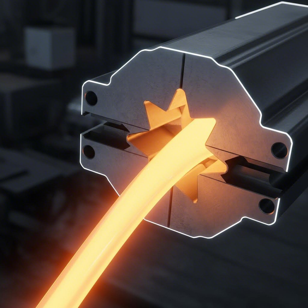
Now that you understand what tolerance values to expect, here's the question that separates informed engineers from frustrated ones: Why do these variations occur in the first place? When you grasp the manufacturing realities behind aluminum extrusion design guidelines, you'll make smarter decisions about which tolerances actually matter for your application.
Think of the extrusion process like squeezing toothpaste through a shaped nozzle. Sounds simple? In reality, countless variables influence whether your profile aluminum extrusion emerges within specification or requires costly rework. Let's examine the primary factors that determine achievable tolerances.
The die is where tolerance control begins. According to Engineers Edge, setup costs for extrusions are expensive primarily due to tooling quality requirements. A well-designed die doesn't just create your desired shape. It manages metal flow to ensure dimensional consistency across thousands of linear feet of production.
Here's what happens inside the die: heated aluminum flows through the opening at varying speeds depending on the geometry. Metal moves faster through larger openings and slower through thin sections. If the die design doesn't account for these flow differentials, wall thickness becomes uneven, and cross-sectional dimensions drift outside tolerance.
Wall thickness uniformity relates directly to die quality. When one section of your profile consistently runs thicker or thinner than specified, the culprit is usually unbalanced metal flow at the die. Experienced die designers use bearing lengths, flow deflectors, and pocket depths to equalize material velocity across the entire cross section.
The key process variables affecting tolerance control include:
Understanding these variables explains why the aluminium extrusion design guidelines recommend liberal tolerances whenever possible. Each variable introduces potential variation, and their effects compound throughout the process.
Not all aluminum alloys extrude equally. The alloy you specify significantly impacts achievable tolerances, and this connection is something most tolerance charts fail to explain. Here's the practical insight: softer alloys generally achieve tighter tolerances than harder alloys.
Why? According to Orange Aluminum's technical comparison, aluminum 6063 is the most extrudable alloy available. Its chemical composition creates a "softer" material that flows smoothly through complex die geometries. This superior flow characteristics translates directly to better dimensional control and more consistent extruded aluminum sizes.
Compare this to 6061 alloy, which offers greater strength but contains higher concentrations of magnesium and silicon. The increased alloying elements make the material harder and more resistant to deformation. While this benefits structural applications, it means the metal doesn't flow as uniformly through the die, making tight tolerance control more challenging.
The relationship between alloy and tolerance looks like this in practice:
Temper selection also affects your tolerance outcomes. Annealed (O temper) material is softer and more malleable, which sounds beneficial until you consider the tolerance implications. The Aluminum Association specifies straightness tolerances for O temper at 0.050 inches per foot compared to 0.0125 inches per foot for heat-treated tempers. That's four times the allowable deviation.
Heat-treatable alloys like 6063-T5 and 6061-T6 undergo thermal processing that stabilizes their dimensions. This heat treatment actually improves tolerance consistency because it relieves internal stresses that might otherwise cause post-extrusion warping or dimensional changes.
The practical takeaway? When your aluminum extrusion design requires the tightest possible tolerances, specify 6063-T5 or 6063-T6 whenever strength requirements permit. You'll benefit from superior extrudability, excellent surface finish, and the dimensional stability that comes from proper heat treatment. Reserve harder alloys for applications where mechanical properties genuinely demand them, accepting the tolerance trade-offs that come with that choice.
Armed with this understanding of what causes tolerance variations, you're ready to apply these insights practically. The next step is learning how to read tolerance charts effectively and decide when standard tolerances work versus when precision specifications are worth their added cost.
You've got the tolerance values. You understand what causes variations. Now comes the practical question every engineer faces: How do you actually use this information to write specifications that work? Reading an aluminum extrusion catalog or standard aluminum extrusion profiles PDF is one thing. Translating those numbers into specifications that balance functionality, cost, and manufacturability is another skill entirely.
Whether you're launching a new project or troubleshooting parts that arrived out of spec, the approach differs significantly. Let's break down both scenarios so you can make confident decisions every time you specify aluminum extrusion sizes.
Before diving into decision frameworks, you need to master the mechanics of reading tolerance charts correctly. Sounds straightforward? Many specification errors stem from misinterpreting the data itself.
Here's a step-by-step approach to reading tolerance charts accurately:
When reviewing standard aluminium extrusions, pay attention to footnotes. Many tolerance tables include conditions that modify the base values. For instance, wall thickness tolerances often increase when one wall is substantially thicker than an opposing wall.
For new projects, your goal is specifying tolerances that ensure proper fit and function without overconstraining the manufacturer. Start by asking these questions:
For troubleshooting out-of-spec parts, the approach reverses. You're working backward from a problem to identify the root cause. Check measurements against the correct tolerance table for your profile type and CCD. According to industry tolerance guidelines, wall thickness variations and twist over length are among the most common areas where deviations occur. Verify your supplier used the same reference standard you specified.
Here's where cost-conscious engineering meets functional requirements. According to Alexandria Industries, "adding tight tolerances on non-critical dimensions is a major source of hidden costs." These unnecessary constraints can result in print deviations, longer setups, reruns, costly die trials, and ultimately price increases.
The decision framework comes down to one fundamental question: What functional requirement drives this tolerance specification?
| Tolerance Level | Typical Applications | Cost Implications | Lead Time Impact |
|---|---|---|---|
| Standard Tolerances | Architectural frames, general structural components, non-critical assemblies, decorative trim | Baseline pricing; no premium | Standard lead times; readily available from stock profiles |
| Precision Tolerances | Sliding mechanisms, bearing housings, heat sink interfaces, close-fit assemblies | 15-30% premium typical; requires enhanced die maintenance and slower press speeds | Extended lead times for die qualification; capability studies may be required |
| Ultra-Precision Tolerances | Aerospace components, optical equipment, medical devices, high-precision instrumentation | 50-100%+ premium; may require secondary machining to achieve final dimensions | Significant lead time extension; often requires capability studies and specialized inspection |
Why do tighter tolerances cost more? The manufacturing reality is straightforward. As industry experts explain, achieving tighter tolerances demands more precise tooling, slower machine speeds, more die maintenance, higher scrap rates, and more inspection. All of these factors add time and expense.
Consider the CpK (process capability index) implications. According to tolerance specification best practices, a 1.33 CpK requirement effectively reduces your tolerance band to 75 percent of the stated value. A 1.67 CpK requirement shrinks it to just 60 percent. When you specify both tight tolerances and high CpK values, you're compounding the manufacturing challenge.
Use this practical decision checklist before specifying precision tolerances:
The most effective approach? Partner with your extruder early in the design stage. As industry guidance emphasizes, "having discussions with your aluminum extruder in the design/quoting stage to agree on tight tolerance features is important." Some manufacturers can hold tighter tolerances than standards require, while others may struggle with specific geometries. Early collaboration identifies the most cost-effective path to your functional requirements.
When you do specify precision tolerances, establish a tolerance hierarchy. Identify your primary, secondary, and tertiary datums. This tells manufacturers which dimensions matter most when trade-offs become necessary during production. Clear prioritization reduces process variation and keeps costs down by minimizing excess operations.
With your tolerance selection strategy defined, the next consideration is how these requirements translate across different industries and applications. What works for architectural installations differs significantly from aerospace or industrial equipment demands.

You've mastered tolerance values and selection strategies. But here's what transforms good specifications into great ones: understanding how tolerance requirements shift dramatically across different industries. A dimension that demands precision control in aerospace might be completely non-critical in building construction. Recognizing these distinctions prevents both overspecification that wastes money and underspecification that causes failures.
Why do industries prioritize tolerances so differently? It comes down to functional demands, safety requirements, and economic realities. Let's explore how various sectors approach aluminum extrusion tube, bar, and profile specifications.
Each industry has developed its own tolerance philosophy based on decades of experience with what actually matters for their applications. Understanding these patterns helps you benchmark your own requirements against proven practices.
Aerospace and Defense: This sector represents the most demanding tolerance environment. According to the Aluminum Extrusion Council, many extruders can achieve tighter tolerances than indicated in standard tables when required. Aerospace specifications like AMS-QQ-A-200/3 for 2024 alloy extrusions often reference precision tolerances as the baseline, with additional callouts for ultra-precision on flight-critical dimensions.
What makes aerospace different? Components may experience extreme temperature cycling, high-frequency vibration, and substantial loading. An aluminum extrusion tube serving as structural aircraft framing must maintain dimensional stability across operating conditions. Tolerance stack-ups in assemblies with hundreds of mating parts demand precision control at each interface.
Transportation: Automotive, rail, and marine applications balance performance requirements against cost pressures more aggressively than aerospace. Structural aluminium extrusions in vehicle frames typically specify precision tolerances for mounting interfaces while accepting standard tolerances elsewhere. The aluminum tube profiles used in railcar construction prioritize straightness and twist control because these affect both assembly fit and ride quality.
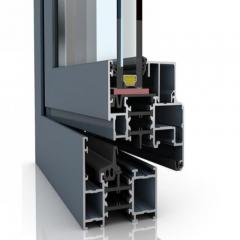
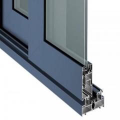
Building and Construction: Architectural aluminum extrusions represent the highest volume segment of the industry. Here's the practical reality: standard tolerances work perfectly for most applications. Window frames, curtain wall systems, and storefront assemblies are designed with gaskets, sealants, and adjustable connections that accommodate normal dimensional variation.
When building with aluminum extrusion for architectural applications, designers focus tolerance attention on visible surfaces and weatherseal interfaces rather than overall dimensional precision. Aluminum panel extrusions for facade systems might specify precision flatness tolerances while accepting standard values for thickness and width.
Industrial Equipment: Manufacturing machinery, conveyor systems, and process equipment occupy a middle ground. Critical bearing surfaces and slide mechanisms demand precision tolerances. Structural framework typically uses standard tolerances with strategic machining where precision interfaces are required.
| Profile Type | Primary Applications | Typical Tolerance Level | Critical Dimensions | Common Tolerance Approach |
|---|---|---|---|---|
| Round Tubes | Pneumatic cylinders, bearing housings, structural frames | Standard to Precision | OD, ID, concentricity | Standard for structural; precision for sliding/sealing applications |
| Square/Rectangular Tubes | Frames, rails, enclosures | Standard | Corner radii, flatness | Standard tolerances with secondary machining at connection points |
| Solid Bars | Machining stock, structural members, handles | Standard to Precision | Diameter, straightness | Standard for machining stock; precision for direct-use applications |
| Architectural Profiles | Window frames, curtain walls, storefronts, handrails | Standard | Visible surfaces, gasket grooves | Standard tolerances with attention to surface finish quality |
| Structural Shapes | Building frames, bridges, industrial structures | Standard | Straightness, twist | Standard tolerances per ASTM B308 for structural profiles |
| Heat Sink Profiles | Electronics cooling, LED lighting, power systems | Precision | Flatness, fin spacing | Precision flatness for thermal interface; standard for overall dimensions |
| Aerospace Profiles | Aircraft structure, missile components, satellite systems | Precision to Ultra-Precision | All interfacing dimensions | Precision minimum; ultra-precision for flight-critical interfaces |
Selecting appropriate tolerances requires matching your profile type's characteristics to your application's actual demands. Let's examine the specific considerations for common profile categories.
Aluminum Extrusion Tube Considerations: Tubes present unique tolerance challenges because you're controlling both inside and outside dimensions simultaneously. According to Aluminum Association Table 12.2, when outside diameter, inside diameter, and wall thickness are all specified, standard tolerances apply to only two of these three dimensions. You must decide which two matter most.
For aluminum tube profiles used in pneumatic or hydraulic applications, the inside diameter typically takes priority because it affects flow characteristics and seal engagement. Structural applications might prioritize outside diameter for consistent fit within mounting brackets. Wall thickness becomes critical when the tube carries significant loads.
Extruded Bar Specifications: Solid bars used for machining stock often need only standard tolerances because subsequent CNC operations will create final dimensions. However, bars used directly in assemblies require more careful specification. Straightness tolerance becomes particularly important for longer bars to ensure proper alignment in machinery applications.
Architectural Aluminum Extrusions: These profiles prioritize visual quality and weatherproofing performance over dimensional precision. Gasket groove dimensions need sufficient accuracy for proper seal compression, but overall frame dimensions accommodate adjustment during installation. The tolerance focus shifts to surface roughness (Table 11.10 specifies maximum depths for die lines and handling marks) and corner radii consistency for aesthetic uniformity.
Consider how different industries prioritize the same tolerance dimensions:
The practical lesson? Industry-appropriate tolerance selection starts with understanding what actually drives performance in your application sector. Architectural aluminum extrusions succeed with standard tolerances because the entire design philosophy accommodates variation through adjustable connections and flexible sealants. Aerospace components demand precision because designs assume minimal variation at every interface.
When you're uncertain about appropriate tolerance levels for your application, look at similar successful products in your industry. What tolerances do established competitors specify? Which dimensions do they call out for precision control, and which accept standard values? This competitive benchmarking often reveals more practical insight than theoretical analysis.
Sometimes standard extrusion tolerances simply cannot achieve what your application requires. When that happens, secondary operations offer a path to precision that extrusion alone cannot provide. Understanding these options expands your design flexibility while keeping base extrusion costs reasonable.
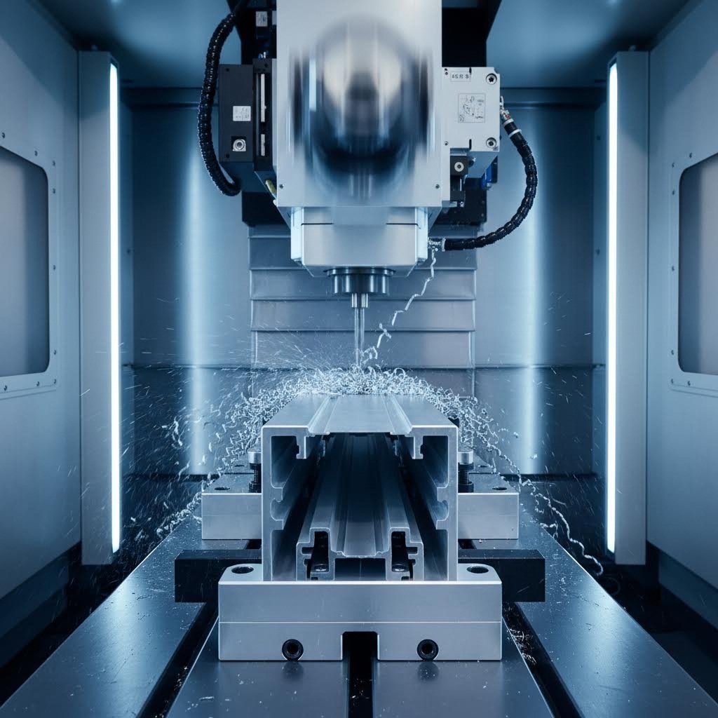
What happens when your application demands tolerances tighter than standard extrusion can deliver? You don't abandon aluminum extrusion entirely. Instead, you combine it with secondary processing operations that refine critical dimensions to precision specifications. This approach gives you the best of both worlds: cost-effective near-net-shape extrusion for the overall profile, plus machined accuracy exactly where your design requires it.
According to industry tolerance specialists, typical post-machining tolerances for CNC machined aluminum extrusions range from ±0.05 mm to ±0.10 mm on linear dimensions. Fine machining can achieve ±0.02 mm on selected features when design, process, and inspection are properly aligned. These capabilities transform stock aluminum extrusion profiles into precision components that meet demanding specifications.
CNC machining stands as the most capable method for achieving tight tolerances on aluminum extrusions. Modern CNC centers deliver positioning accuracy within ±0.005 mm, but true precision depends on more than machine capability alone. Calibration frequency, spindle rigidity, thermal compensation, and fixturing quality all influence your final results.
Here's what makes CNC machining particularly effective for aluminum tube extrusion and extruded aluminum bar applications:
Why does fixturing matter so much? Aluminum extrusions are often long and flexible. According to machining tolerance experts, improper clamping causes vibration or part distortion. Poor fixtures lead to bending during cutting, and when released, the part springs back to a different measured size. Custom fixtures, vacuum plates, and soft jaws help maintain alignment during machining, especially for thin-wall aluminum parts.
Thermal considerations also affect precision. Aluminum expands approximately 23 µm per meter per degree Celsius. A 1-meter part can grow 0.023 mm per degree of temperature rise. For critical tolerance work, machining and inspection should occur under controlled room temperature, typically 20°C ±1°C.
For curved extruded aluminum components, CNC machining becomes essential for achieving compound curves and complex geometries that extrusion alone cannot produce. The combination of extruded base profiles with precision machining enables design flexibility that neither process offers independently.
Beyond CNC machining, several secondary operations contribute to achieving your tolerance requirements. Each offers specific capabilities suited to different manufacturing challenges.
The complete tolerance specification workflow moves from design through production to final verification:
Why does this two-step machining approach matter? According to precision machining guidelines, skipping the rest period between rough and finish machining reduces accuracy. The stress relief step improves dimensional stability, particularly for long or thin parts where movement affects final size.
Manufacturers offering integrated extrusion and deep processing capabilities provide significant advantages for tolerance-critical projects. Shengxin Aluminium's deep processing services exemplify this integrated approach, combining 35 extrusion presses ranging from 600T to 5500T capacity with state-of-the-art CNC machining centers for precise cutting, drilling, and bending. Having extrusion and precision processing under one roof eliminates the dimensional variations that occur when parts transfer between separate facilities.
This integration matters because bringing secondary operations in-house typically reduces lead times by over 50% compared to outsourced processing. Jobs once delayed by days can begin the same day or even within the same hour. For aluminum bar extrusions requiring precision machining, this consolidated approach ensures consistent quality control from raw billet through finished component.
Inspection verification closes the loop on your tolerance specification workflow. Post-machining dimensions require verification using appropriate measurement tools:
One critical note: inspection should occur after final machining but before surface treatment. Anodizing and coating add thickness that affects measured dimensions. Clear agreement on inspection stage between supplier and customer avoids disputes about conformance.
Understanding when to apply secondary operations versus accepting extrusion tolerances requires balancing cost, lead time, and functional requirements. With your knowledge of both standard tolerances and secondary processing capabilities, you're equipped to make these decisions strategically. The next consideration is selecting tolerances based on your specific profile shapes and project requirements.
You've studied the tolerance charts, understood the manufacturing variables, and explored secondary processing options. Now comes the moment of truth: making actual tolerance decisions for your specific project. How do you balance functional requirements against cost pressures and delivery timelines? The answer lies in a systematic approach that considers profile geometry, application demands, and effective supplier communication.
Different profile shapes present unique tolerance challenges. A square aluminum extrusion behaves differently during extrusion than an aluminum extrusion round profile. Understanding these geometry-specific considerations helps you specify tolerances that are both achievable and appropriate for your application.
Before specifying any tolerance value, ask yourself one essential question: What happens if this dimension falls at the extreme edge of the tolerance band? If the answer is "nothing significant," you've identified a candidate for standard tolerances. If the answer involves assembly failure, performance degradation, or safety concerns, that dimension deserves tighter specification.
Here's a practical framework for tolerance selection that balances competing priorities:
Cost, lead time, and precision form an interconnected triangle. Tightening any tolerance affects the other two factors. According to industry tolerance guidelines, moving from standard to precision tolerances can increase costs by 30% to 200%, with some ultra-precision requirements pushing costs two to five times higher. These premiums reflect slower extrusion speeds, more frequent die maintenance, higher rejection rates, and additional inspection requirements.
Lead time impacts follow similar patterns. Stock aluminium extrusion profiles ship quickly because they're produced in volume with standard tolerances. Custom precision work requires capability studies, die qualification runs, and specialized inspection protocols that extend delivery schedules significantly.
Each profile geometry presents distinct tolerance challenges. Understanding these shape-specific factors helps you write specifications that manufacturers can actually achieve.
| Profile Shape | Typical Tolerance Challenges | Specification Tips | Common Applications |
|---|---|---|---|
| Aluminum Extrusion Round | Ovality (out-of-round condition); concentricity between OD and ID for tubes | Specify either OD or ID as primary control dimension; accept standard tolerance on the other. For concentricity-critical applications, specify TIR (Total Indicator Runout). | Pneumatic cylinders, bearing housings, rollers, structural tubes |
| Square Aluminum Extrusion | Corner radii consistency; wall thickness uniformity on hollow sections; maintaining 90° angles | Accept industry-standard corner radii unless cosmetic requirements demand sharper corners. Specify wall thickness tolerance on critical structural walls only. | Framing systems, enclosures, structural supports, machine guards |
| Aluminum T Bar Extrusion | Web-to-flange perpendicularity; unequal cooling causing twist; flange straightness | Prioritize perpendicularity tolerance when T-bar serves as a guide or track. Accept standard straightness unless the profile serves precision linear motion applications. | Structural reinforcement, sliding tracks, edge trim, framing connections |
| Aluminum H Extrusion | Parallel flange spacing; uniform web thickness; symmetry between opposing flanges | Specify flange spacing tolerance when the profile captures panels or mating components. Control web thickness when structural loading is significant. | Panel mounting channels, double-sided tracks, structural beams, connector profiles |
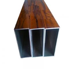
| Aluminium Extrusion Tube (Rectangular) | Corner bulging during extrusion; uneven wall distribution; twist over length | When specifying wall thickness, identify which walls are structurally critical. Accept larger tolerance on non-load-bearing walls to reduce cost. | Structural frames, handrails, furniture, equipment enclosures |
| Complex Custom Profiles | Thin sections distorting; asymmetric cooling; deep channels collapsing | Work with your extruder during design to identify tolerance-critical features. Consider adding sacrificial material for post-machining of precision surfaces. | Heat sinks, specialized industrial components, architectural details |
Notice how aluminum extrusion bar specifications differ from hollow profiles. Solid bars offer more consistent dimensional control because there's no internal void creating differential cooling. An aluminum extrusion bar used for machining stock typically needs only straightness control, while the same bar used directly in an assembly requires attention to cross-sectional dimensions as well.
For aluminium extrusion tube applications, the interrelationship between outside diameter, inside diameter, and wall thickness creates specification complexity. You cannot independently control all three dimensions because they're mathematically related. Decide which two dimensions matter most for your application and specify tolerances on those, allowing the third to float within the resulting range.
Clear communication prevents costly misunderstandings. When submitting tolerance specifications to your extrusion supplier, include these essential elements:
What documentation should you request from suppliers? At minimum, ask for:
Supplier partnership quality directly impacts your tolerance success. Working with manufacturers who provide end-to-end technical support from die development through mass production ensures tolerance requirements are addressed at every production stage. Shengxin Aluminium exemplifies this integrated approach, bringing over 30 years of experience with custom 6063 aluminum tubes and complex industrial profiles. Their technical team supports customers from initial die design through production optimization, ensuring tolerance specifications translate into conforming parts rather than rejected shipments.
According to aluminum extrusion design tolerance experts, engaging with your manufacturing partner early in the design process provides valuable feedback on manufacturability. This collaboration helps prevent costly redesigns and production delays. An experienced extruder can often suggest minor design modifications that dramatically improve tolerance achievability without affecting your functional requirements.
The practical takeaway? Tolerance selection isn't just a technical exercise. It's a communication challenge that requires clear documentation, realistic expectations, and collaborative supplier relationships. When you specify tolerances that reflect genuine functional requirements, communicate them clearly through proper documentation, and partner with capable manufacturers, your aluminum extrusion projects succeed without the costly surprises that plague overspecified or poorly communicated designs.
Standard aluminum extrusion tolerances vary by dimension type and profile complexity. For cross-sectional metal dimensions on profiles with circumscribing circles under 10 inches, tolerances range from ±0.006 inches for dimensions up to 0.124 inches to ±0.024 inches for dimensions between 2.000-3.999 inches. Straightness tolerance is typically 0.0125 inches per foot of length. Wall thickness tolerances generally run 10-15% of the specified dimension. Precision tolerances can reduce these values by approximately 30-40%, while ultra-precision specifications achieved through secondary machining can reach ±0.001 inches on critical features.
ASTM B221 is the primary standard specification for aluminum and aluminum-alloy extruded bars, rods, wire, profiles, and tubes. This standard works in conjunction with ANSI H35.2-2024, which provides comprehensive dimensional tolerance tables. The Aluminum Association develops the technical content referenced in these standards, including Tables 11.2-11.14 for profiles and Tables 12.2-12.14 for tubes and pipes. For aerospace applications, additional specifications like AMS-QQ-A-225/8 for 6061 alloy and AMS-QQ-A-200/3 for 2024 alloy provide tighter tolerance requirements.
Standard aluminum extrusions achieve tolerances of ±0.008 inches per inch on linear cross-sectional dimensions. Precision extrusions can achieve approximately 30-40% tighter tolerances through enhanced die maintenance and slower press speeds. Ultra-precision capabilities using micro-extrusion presses can produce wall thicknesses of 0.020 inches with tolerances of ±0.001 inches. When combined with CNC machining, post-processing tolerances of ±0.05 mm to ±0.02 mm are achievable on critical dimensions. Alloy selection affects precision, with 6063 offering superior extrudability and tighter tolerance control compared to harder alloys like 6061 or 7075.
Multiple manufacturing variables influence achievable tolerances. Die design and bearing length control metal flow uniformity and wall thickness consistency. Alloy selection matters significantly, with softer 6063 achieving tighter tolerances than harder alloys. Billet temperature (750-925°F) affects material flow behavior. Extrusion speed impacts heat generation and dimensional stability. Cooling rate uniformity prevents warping and twist. The stretching process after extrusion improves straightness but can alter cross-sectional dimensions. Die wear over production runs gradually enlarges dimensions, requiring regular maintenance for consistent tolerance control.
Specify precision tolerances only when functional requirements genuinely demand them. Critical applications include sliding mechanisms, bearing housings, press-fit assemblies, thermal interfaces for heat sinks, and aerospace structural components. Standard tolerances suffice for architectural frames, general structural members, welded assemblies, and surfaces that will receive secondary machining. Precision tolerances typically add 15-30% cost premium with extended lead times, while ultra-precision specifications can increase costs 50-100% or more. Always identify which dimensions are truly critical and apply tight tolerances selectively rather than blanket-specifying precision across all features.



 serviço on-line
 0086 136 3563 2360
 sales@sxalu.com
 +86 136 3563 2360
 português
 English
 français
 Deutsch
 русский
 español
 العربية
 ไทย
ไทย Việt
Việt Українська