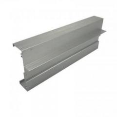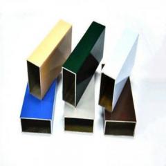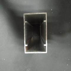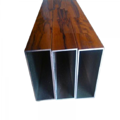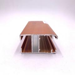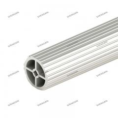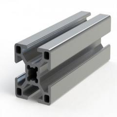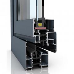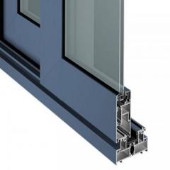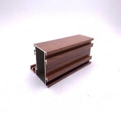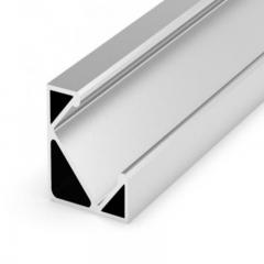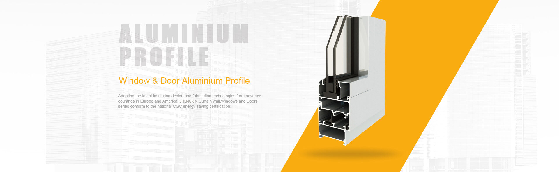
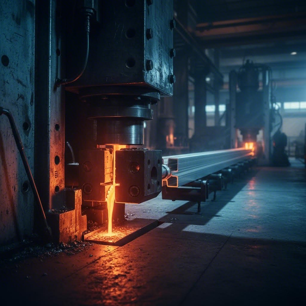
Aluminum extrusion design guidelines are the engineering principles and specifications that govern how profiles are created when heated aluminum is pushed through a steel die. For engineers, architects, and product designers, these guidelines serve as the foundation for developing components that perform reliably while remaining cost-effective to manufacture. When you understand these principles, you unlock the ability to create everything from simple bars to complex hollow sections with remarkable precision.
Think of it this way: proper design guidelines prevent costly manufacturing errors, reduce tooling expenses, and ensure optimal performance throughout your product's lifecycle. According to the Aluminum Extruders Council's Extrusion Manual, while casting tools can exceed $30,000, custom extrusion dies often cost between $500 and $5,000, making informed design decisions incredibly valuable from day one.
The aluminum extrusion process involves forcing heated, malleable aluminum alloy through a steel die using hydraulic pressure ranging from 100 to 15,000 tons. The resulting profile assumes the exact cross-sectional shape of the die opening. Unlike other forming methods, this process allows designers to create near-net shapes with complex geometries in a single operation.
What sets this process apart? You can put metal precisely where it's needed, eliminating the joints, welds, and secondary operations required by alternative manufacturing methods. The extrusion process follows these essential steps:
This aluminium extrusion design guide exists because every decision you make during design directly influences how metal flows through that die. Sharp corners, unbalanced wall thicknesses, or overly complex geometries can cause uneven material flow, leading to defects, increased scrap rates, and premature die failure.
Here's what many engineers miss: the aluminum extrusion design decisions you make in the earliest stages have the greatest impact on final cost and quality. Unlike machining, where you can adjust parameters mid-production, extrusion requires getting it right before the die is ever cut.
Design decisions made during the initial concept phase determine up to 90% of your total extrusion costs, including die life, production speed, scrap rates, and secondary processing requirements.
Consider how understanding the aluminum extrusion process shapes your design approach. When aluminum flows through a die, the material at the center advances more rapidly than at the edges. This natural behavior means asymmetric profiles or sections with dramatically different wall thicknesses can create flow imbalances, resulting in warping, twisting, or dimensional inconsistencies.
Following established design guidelines delivers measurable benefits:
The sections that follow will walk you through specific principles, from wall thickness optimization to alloy selection, each building on this fundamental understanding of how aluminum behaves during extrusion. Whether you're designing a simple channel or a complex multi-void hollow section, these guidelines will help you create profiles that perform exceptionally while remaining economical to produce.
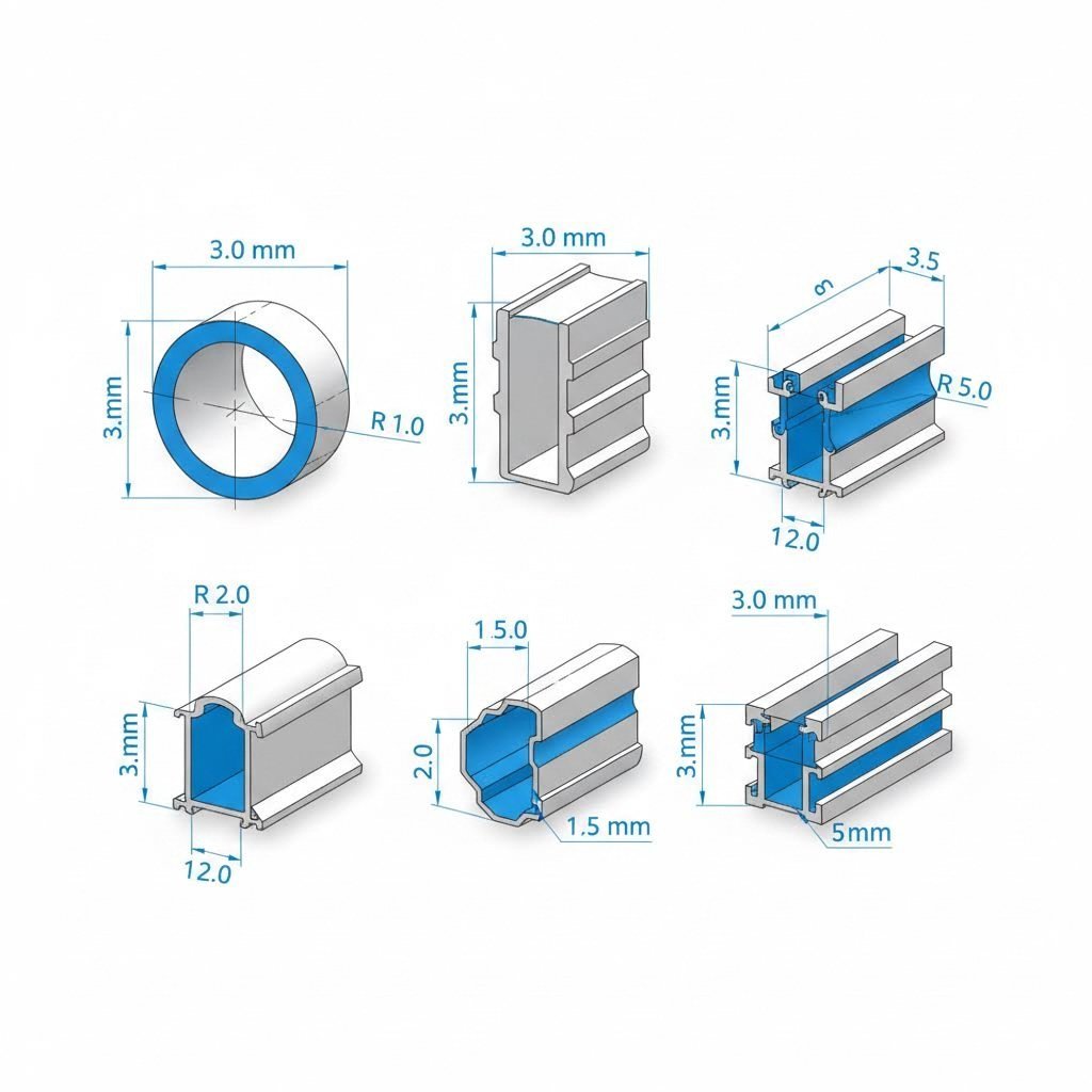
When designing aluminum extrusion profiles, wall thickness is arguably the most critical variable you'll control. Why? Because wall thickness directly determines how metal flows through the die, how quickly you can run production, and ultimately how long your tooling will last. Get this right, and you'll enjoy smooth production runs with consistent quality. Get it wrong, and you're looking at warped profiles, premature die wear, and escalating costs.
The fundamental principle here is straightforward: uniform wall thickness promotes even metal flow. When aluminum moves through a die at consistent speeds across the entire cross-section, internal stresses remain balanced, and the profile cools uniformly. This prevents the warping and twisting that plague designs with dramatic thickness variations.
You might wonder, "How thin can I go?" The answer depends primarily on your profile's circumscribing circle diameter, which is the smallest circle that completely encloses your extrusion's cross-section. Larger profiles require thicker minimum walls because the aluminum must travel farther from the die opening's edges while maintaining structural integrity.
According to industry standards from Bonnell Aluminum, minimum wall thickness increases progressively with profile size. The relationship also differs between solid, semi-hollow, and hollow shapes, with hollows requiring thicker walls to accommodate the more complex die construction.
| Circumscribing Circle (inches) | Solids & Semi-hollows (min.) | Class 2 Hollows (min.) |
|---|---|---|
| 0.5 to under 2 | 0.040" | 0.055" |
| 2 to under 3 | 0.045" | 0.062" |
| 3 to under 4 | 0.050" | 0.078" |
| 4 to under 5 | 0.062" | 0.094" |
| 5 to under 6 | 0.078" | 0.110" |
| 6 to under 7 | 0.094" | 0.125" |
| 7 to under 8 | 0.110" | 0.140" |
| 8 to under 9 | 0.125" | 0.156" |
| 9 to under 10 | 0.140" | 0.188" |
| 10 to under 12 | 0.156" - 0.172" | 0.204" - 0.220" |
| 12 and above | Subject to inquiry | Subject to inquiry |
For aluminum profile extrusions, keep in mind that these represent practical minimums. Your specific application may require thicker walls for structural performance, and certain alloys like 6061 often need slightly heavier sections than the more extrudable 6063.
Here's where understanding the "why" behind these guidelines really pays off. Thinner walls don't just push manufacturing limits; they fundamentally change the economics of your project.
When you specify thinner walls, several cost factors come into play:
Equally important is maintaining balanced wall thickness ratios across your profile. According to industry guidelines, adjacent wall thickness ratios greater than 2:1 should be avoided. When thick and thin sections meet, the thicker area cools more slowly, creating internal stresses that can cause distortion or dimensional instability.
If your design requires varying aluminum extrusion dimensions, use gradual transitions with rounded corners where different thicknesses meet. This approach eases metal flow through the die and reduces visible streaking on the opposite surface, a common defect that occurs when abrupt thickness changes create turbulent flow patterns.
Another practical consideration is profile weight-per-foot. As noted by Xometry's design guidelines, keeping your profile between 0.100 lbs/ft and 3 lbs/ft optimizes press efficiency. Heavier profiles strain equipment and limit extrusion rates, while extremely light profiles may lack the stiffness needed for consistent handling during production.
By specifying the minimum wall thickness that meets your structural requirements while maintaining balanced proportions throughout extruded aluminum sizes, you'll achieve the sweet spot between material efficiency and manufacturing practicality. This balance sets the stage for the next critical decision: whether your application calls for a hollow or solid profile configuration.
One of the most impactful choices you'll make when designing an extruded profile is whether to specify a hollow or solid cross-section. This decision affects everything from die cost and production speed to your component's structural performance and weight. Understanding when each option makes sense, and how to design effective internal geometries, will help you maximize value while avoiding costly mistakes.
The key difference lies in how these profiles are manufactured. Solid profiles emerge from simpler flat-face dies, while hollow profiles require porthole or bridge dies that split the aluminum flow around mandrel supports before rejoining it in a welding chamber. This added complexity increases tooling costs, but the engineering benefits often justify the investment.
Hollow aluminum profile extrusion offers distinct advantages that make it the preferred choice for many structural and functional applications. According to LA Metals' guide on hollow extrusions, the unmatched strength-to-weight ratio is the primary driver behind their widespread adoption in construction, automotive, and fabrication industries.
Consider choosing hollow extrusion shapes when your application requires:
However, solid aluminum extruded profiles remain the better choice in certain scenarios:
Once you've decided a hollow configuration suits your needs, the next challenge is designing internal geometries that are both functional and manufacturable. Research from the International Journal of Advanced Manufacturing Technology demonstrates how internal web placement and chamber design directly impact die strength and metal flow behavior.
The tongue ratio is critical when designing semi-hollow sections, those profiles that partially enclose a void. This ratio compares the area of the partially enclosed space to the square of the gap opening (Area/Gap²). According to the Aluminum Extrusion Manual, profiles exceeding specific tongue ratio thresholds are classified as semi-hollow and require more robust die construction to prevent tongue deflection or breakage during extrusion.
For effective internal chamber design, follow these principles:
The relationship between void size and wall thickness also deserves attention. Larger internal chambers relative to wall thickness create greater die deflection during extrusion. Studies on porthole die design show that optimizing pocket shape, bearing length, and die runout angles can dramatically improve metal flow uniformity and reduce the extrusion force required, sometimes by more than 7% compared to initial designs.
When specifying a hollow extruded profile, communicate clearly with your extruder about functional requirements. They can advise whether your internal geometry will require a porthole die with multiple legs supporting the mandrel, or if a simpler bridge die configuration will suffice. This collaboration early in design prevents surprises when tooling quotes arrive and ensures your profile can be manufactured consistently at the quality level your application demands.
With your profile configuration determined, the next consideration is understanding how die constraints and corner radii requirements further shape the geometries you can practically achieve.
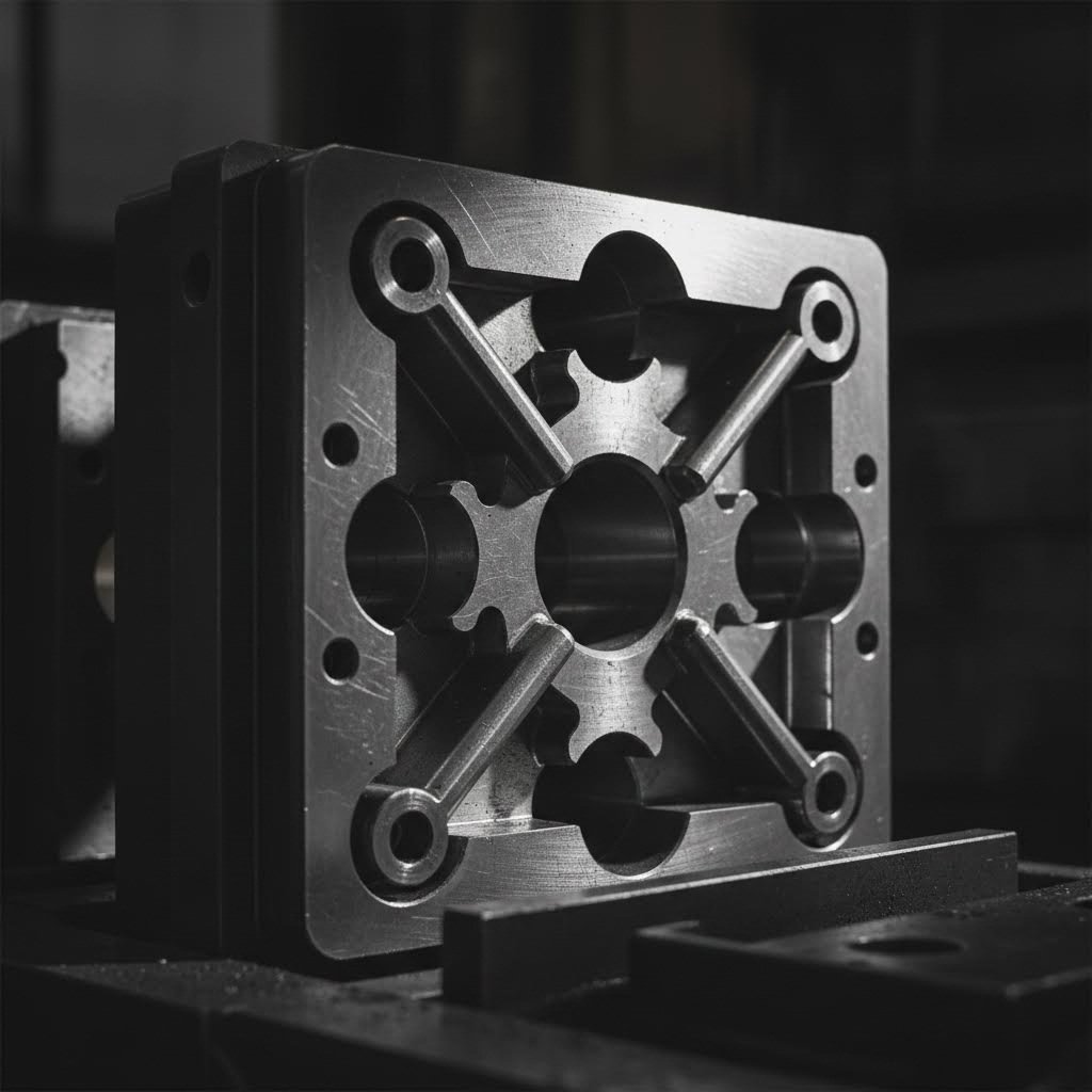
Every extrusion profile you design must ultimately be cut into a steel die, and that die must survive the intense pressures and temperatures of production. Understanding these aluminum extrusion die constraints isn't just academic knowledge; it's the difference between a design that runs smoothly and one that causes repeated tooling failures, production delays, and budget overruns.
Think of the die as the bottleneck of your entire project. No matter how elegant your design looks on screen, if the die can't hold up under production conditions or if the metal can't flow evenly through your specified geometry, you'll face problems. According to Profile Precision Extrusions, most custom dies range from $1,250 to $1,950, but complex profiles with multiple hollows, tight corners, or asymmetric features can push costs significantly higher.
The extrusion die design process involves balancing several competing factors: the geometry you need, the forces the die must withstand, and the flow characteristics of heated aluminum. Each feature you add to your extrusion profile creates additional stress points in the tooling.
Profile complexity directly correlates with die cost and lifespan. Here's what drives that relationship:
The tongue ratio becomes especially important when designing semi-hollow sections. As noted by PT Damai Abadi's design guide, profiles with deep, narrow channels (high tongue ratios) create weak sections in the die that are prone to deflection. Engineers should aim for a tongue ratio of less than 3:1 to improve die strength and ensure consistent metal flow throughout production runs.
Asymmetric designs present particular challenges for aluminum extrusion tooling. When your profile lacks symmetry, the metal naturally flows faster through areas with less resistance, creating imbalanced pressure distribution across the die face. This imbalance causes several problems:
If asymmetry is unavoidable in your design, consider incorporating subtle balancing features. Slightly thicker sections near the profile center or strategic placement of ribs can help equalize flow resistance and reduce stress concentrations in the die.
Sharp internal corners are perhaps the most common design error that leads to premature die failure. When aluminum is forced around a tight corner, both the die steel and the finished part experience concentrated stress at that point. Over thousands of extrusion cycles, this stress concentration causes cracking, erosion, and dimensional drift.
According to industry best practices, a minimum inside radius of 0.5mm to 1mm (approximately 0.020" to 0.040") is recommended for most profiles. However, larger radii are always preferable when your design permits. The general rule: specify the largest internal radius your functional requirements will allow.
External corners also benefit from radii, though they're somewhat more forgiving than internal angles. Rounded external corners:
Where walls of different thickness must meet, gradual transitions with generous radii ease metal flow and prevent the streaking defects that occur when aluminum encounters abrupt geometry changes. Rather than stepping directly from a 0.125" wall to a 0.062" wall, design a gradual taper with a radius at each transition point.
To help guide your design decisions, here's a comparison of features that impact die for aluminium extrusion complexity and cost:
Working with your extrusion partner during the design phase pays dividends here. Experienced die designers can often suggest minor geometry modifications that dramatically improve manufacturability without compromising your functional requirements. A slight increase in corner radius or a small adjustment to wall thickness ratios can extend die life by thousands of cycles while reducing your per-piece costs.
With die constraints and corner requirements understood, your next consideration involves selecting the right aluminum alloy, a decision that further defines what geometries and tolerances are practically achievable for your specific application.
You've nailed your wall thickness ratios and corner radii, but here's a question that can make or break your project: which aluminum alloy should you specify? This decision affects far more than just material strength. Your alloy choice directly influences minimum achievable wall thickness, surface finish quality, aluminum extrusion tolerances, and even your aluminum extrusion cost per foot.
The aluminium extrusion process behaves differently depending on which alloy you push through the die. Some alloys flow like butter at extrusion temperatures, allowing complex geometries and thin walls. Others resist flow, demanding simpler profiles and heavier sections to prevent defects. Understanding these differences helps you match material selection to your design requirements from the start.
When engineers ask about extrusion alloys, the conversation almost always centers on two options: 6063 and 6061. According to Howard Precision Metals, these two alloys cover most aluminum extrusion applications, yet they serve distinctly different purposes.
6063 aluminum is the workhorse of the extrusion industry. Alloyed primarily with silicon and magnesium, it offers exceptional extrudability, meaning it flows smoothly through dies at production speeds without tearing or surface defects. This alloy excels in applications where surface finish matters:
What makes 6063 so popular? It accepts anodizing beautifully, producing uniform color and excellent surface reflectivity. It also polishes to a mirror finish when required. However, as industry sources note, 6063 delivers medium strength compared to other alloys and loses up to 30% of its strength when welded.
6061 aluminum steps in when structural performance takes priority over aesthetics. With higher magnesium and silicon content plus copper additions, 6061 provides significantly greater tensile and yield strength. According to the aluminium design manual from Bonnell Aluminum, 6061-T6 achieves ultimate tensile strength of 38 ksi with yield strength of 35 ksi, making it the go-to choice for:
The tradeoff? 6061 is harder to extrude. Its reduced flow characteristics mean you'll typically need thicker walls, simpler geometries, and slower production speeds. Surface finish also suffers compared to 6063, making this alloy less suitable for decorative applications.
Your alloy choice ripples through every aspect of your design specifications. Here's how the decision affects key parameters:
Minimum wall thickness varies significantly between alloys. While 6063 can achieve the minimum thicknesses shown in standard reference charts, 6061 typically requires 10-20% heavier walls to ensure proper metal flow and prevent surface defects. If your design pushes wall thickness limits, 6063 gives you more headroom.
Achievable tolerances also depend on alloy selection. The easier an alloy extrudes, the more consistently it fills the die cavity, resulting in tighter dimensional control. 6063's superior flow characteristics typically deliver better tolerance performance than 6061, particularly in complex profiles with varying wall thicknesses.
Surface finish capability differs dramatically. 6063 produces excellent as-extruded surfaces suitable for architectural anodizing, while 6061's higher alloy content can create visible grain structure and surface inconsistencies that require additional finishing operations.
The following table compares common extrusion alloys across key design parameters:
| Alloy | Min. Wall Thickness | Surface Finish | Tensile Strength (T6) | Relative Cost | Best Applications |
|---|---|---|---|---|---|
| 6063 | Standard minimums | Excellent | 30 ksi | Base | Architectural, decorative, thin-wall profiles |
| 6061 | 10-20% above standard | Good | 38 ksi | +5-10% | Structural, aerospace, high-stress applications |
| 6005/6005A | Standard minimums | Good | 38 ksi | +5% | Transportation, structural with good extrudability |
| 6082 | 15% above standard | Fair | 45 ksi | +10-15% | High-strength structural, bridges, cranes |
| 6060 | Standard minimums | Excellent | 30 ksi | Base | Similar to 6063, common in Europe |
Temper selection adds another layer to your decision. The temper designation indicates the thermal and mechanical processing the alloy receives after extrusion. Common tempers include:
According to Bonnell Aluminum's mechanical properties data, a 6063-T6 profile achieves 30 ksi ultimate tensile strength, while the same alloy in T1 temper delivers only 17 ksi. This means temper selection affects not just post-processing requirements but also your structural calculations.
If your application requires significant bending or forming after extrusion, specify T1 or T4 tempers and plan for subsequent heat treatment to achieve final properties. For profiles used as-extruded, T5 or T6 tempers deliver higher strength without additional processing steps.
Matching your alloy and temper to application requirements upfront prevents costly surprises. Specifying 6061 for a decorative architectural profile means accepting surface limitations, while choosing 6063 for a structural application may require increasing wall thickness to compensate for lower strength. The key is making these tradeoffs deliberately during design rather than discovering them during production.
With alloy selection resolved, your next consideration involves designing profiles that achieve superior surface finishes, a topic where your material choice, geometry decisions, and finishing requirements all intersect.
You've selected your alloy and optimized your wall thicknesses, but here's a question that catches many designers off guard: will your profile actually look good after finishing? Surface finish quality isn't just about aesthetics. It affects corrosion resistance, coating adhesion, and customer perception of your final product. The design decisions you've already made directly determine what surface quality you can achieve.
Think about it this way: every alu extrusion profile carries the fingerprint of its journey through the die. Wall thickness variations, corner geometries, and even your alloy choice create conditions that either promote flawless finishes or guarantee visible defects. Understanding these relationships before you finalize your design saves countless hours of troubleshooting during production.
Anodizing and powder coating are the two most common finishing methods for profile aluminum extrusion, but each demands specific design considerations to achieve consistent results.
For anodizing success, uniformity is everything. The anodic layer builds electrochemically, meaning it forms faster in areas where electrical current flows more readily. According to Bonnell Aluminum's design resources, profiles with consistent wall thickness produce more uniform anodized finishes because current distribution remains balanced across the surface.
What happens when wall thickness varies dramatically? Thinner sections anodize more deeply relative to their mass, potentially causing color variations visible to the naked eye. If your aluminum section requires different wall thicknesses, keep the ratio below 2:1 to minimize this effect.
Powder coating presents different challenges. The electrostatic application process means powder particles follow electrical field lines, accumulating heavily on external corners while struggling to reach recessed areas. Design considerations include:
Your alloy choice matters here too. As discussed earlier, 6063 accepts anodizing beautifully, producing uniform color with excellent reflectivity. Using 6061 for a decorative anodized application typically results in a grayer, less consistent appearance due to its higher alloy content.
Die lines are perhaps the most common surface defect in extruded aluminum, appearing as faint longitudinal streaks running the length of your profile. According to research on minimizing extrusion defects, these lines form when the die bearing surface develops microscopic imperfections that transfer to every foot of extruded material.
While die maintenance is the extruder's responsibility, your design choices influence how visible these lines become:
The relationship between profile geometry and coating thickness uniformity deserves special attention. Recessed features like T-slots, screw channels, and decorative grooves create coating challenges. Powder coating thickness in a 0.25" deep channel might be only 40-60% of what accumulates on flat surfaces. If corrosion protection is critical in these areas, consider specifying liquid paint or designing shallower features.
Here's a practical breakdown of design features and their impact on surface finish quality:
Thermal expansion considerations round out your surface finish planning, particularly for alu extrusion profiles used in assemblies. Aluminum expands approximately 0.0000129 inches per inch per degree Fahrenheit, roughly twice the rate of steel. In assemblies combining aluminum extrusions with other materials, this differential creates stress at joints during temperature changes.
What does this mean for your design? If your aluminum profile will be rigidly fastened to steel components in an outdoor application, temperature swings from 20°F to 100°F can create significant differential movement. An 8-foot aluminum section expands about 0.10" more than an equivalent steel member across that temperature range. Without accommodation, this movement causes:
Design solutions include slotted mounting holes that allow longitudinal movement, elastomeric gaskets that absorb differential expansion, and segmented assemblies with expansion joints at appropriate intervals. When specifying joint details, allow approximately 1/16" gap per 4 feet of profile length for outdoor applications with significant temperature variation.
By integrating these surface finish considerations into your design process from the beginning, you'll create profiles that not only extrude well but also accept finishing treatments predictably. This attention to finishing requirements connects directly to structural performance, where your profile geometry must deliver the mechanical properties your application demands.
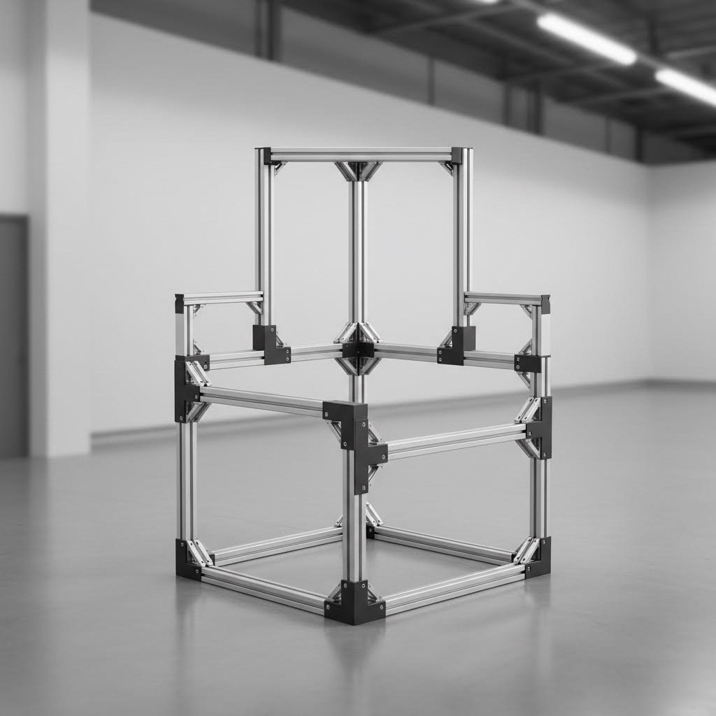
You've optimized your wall thickness, selected the right alloy, and planned for beautiful surface finishes. But here's the question that separates good designs from great ones: will your profile actually perform under load? Understanding how geometry affects structural behavior transforms your aluminum extrusion from a simple shape into an engineered solution that delivers predictable, reliable performance.
Building with aluminum extrusion requires thinking beyond basic dimensions. The same amount of material arranged differently can produce dramatically different structural results. A solid 1" x 1" bar and a hollow 2" x 2" tube might weigh the same, but their resistance to bending differs by an order of magnitude. Strategic material placement is where engineering meets economy.
When loads are applied to your extruded profile, the material's distribution across the cross-section determines how effectively it resists deformation. Two key engineering properties govern this behavior: moment of inertia and section modulus.
Moment of inertia (often denoted as "I") measures a cross-section's resistance to bending. The higher this value, the stiffer your profile becomes under load. According to engineering resources on T-slot profiles, doubling a profile dimension from 20mm to 40mm can increase moment of inertia by more than tenfold. This geometric relationship explains why hollow sections outperform solid ones at equivalent weights.
Section modulus (denoted as "S") relates directly to bending stress. It equals moment of inertia divided by the distance from the neutral axis to the outermost fiber. Higher section modulus means lower stress for a given bending moment, which translates to greater load capacity before yielding.
Imagine you're designing an aluminum extrusion builder frame for automated equipment. Where should you place material for maximum structural efficiency?
The relationship between profile geometry and structural performance follows predictable engineering principles. For large aluminum extrusions used in structural applications, optimizing these properties determines whether your design succeeds or requires costly redesign.
Consider deflection, often the controlling factor in structural design. Even if your profile won't break under load, excessive bending can cause functional problems: misaligned components, binding mechanisms, or simply unacceptable visual sag. The deflection formula for a simply supported beam under uniform load reveals the variables you control:
Deflection = (5 × w × L⁴) / (384 × E × I)
Where:
- w = distributed load per unit length
- L = span length
- E = modulus of elasticity (material property)
- I = moment of inertia (geometry property)
Since aluminum's modulus of elasticity is fixed at approximately 10,000 ksi, and your span length is usually determined by application requirements, moment of inertia becomes your primary design lever. Doubling the moment of inertia cuts deflection in half.
Here's how profile geometry affects these critical properties:
| Profile Type | Relative Weight | Relative Moment of Inertia | Structural Efficiency |
|---|---|---|---|
| 1" × 1" Solid Bar | 1.0 | 1.0 | Baseline |
| 1.5" × 1.5" × 0.125" Tube | 0.69 | 2.1 | 3× better |
| 2" × 2" × 0.125" Tube | 0.94 | 5.3 | 5.6× better |
| 2" × 1" I-Beam (equivalent area) | 1.0 | 4.2 | 4.2× better |
When designing aluminium extrusions profiles for structural applications, consider load direction carefully. A rectangular tube with its long dimension oriented vertically resists vertical loads far better than the same tube rotated 90 degrees. Match your profile orientation to your primary load case.
A profile's structural performance means nothing if you can't connect it effectively to other components. Aluminum extrusion assembly design integrates fastening features directly into the profile cross-section, eliminating secondary machining while ensuring reliable connections.
Screw boss design requires balancing thread engagement with wall thickness limitations. According to Bonnell Aluminum's design guidelines, standard screw slot diameters range from 0.099" for #4 screws to 0.228" for 1/4" fasteners. Key considerations include:
T-slot integration transforms simple extrusions into modular aluminum extrusion builder systems. These standardized channels accept T-nuts and specialized fasteners, enabling infinite adjustment along the profile length. According to T-slot engineering guides, the beauty of this system lies in its adaptability: components can be attached anywhere along the profile and repositioned without drilling new holes.
When designing T-slot features:
Snap-fit features enable tool-free assembly for appropriate applications. These interlocking geometries rely on aluminum's limited elasticity to deflect during insertion, then spring back to capture mating components. Successful snap-fit design requires:
The modular assembly approach exemplified by T-slot systems offers compelling advantages for building with aluminum extrusion. Unlike welded frames requiring specialized skills, bolted T-slot structures assemble with basic hand tools. According to industry experience, assembly using T-slot framing often reduces labor time by 30-50% compared to welded steel construction.
More importantly, these modular systems accommodate change. Need to relocate a sensor mount? Loosen the bolts, slide it along the slot, and retighten. Expanding the frame? Cut a new profile section and bolt it in place. This adaptability proves invaluable for applications where requirements evolve or quick reconfiguration adds operational value.
By integrating structural optimization with thoughtful connection design, your aluminum extrusion becomes more than material formed into a shape. It becomes a complete solution ready for efficient assembly and reliable long-term performance. With these principles in hand, you're prepared to avoid the common design mistakes that derail projects and inflate costs.
You've invested hours perfecting your profile geometry, but here's a reality check: even experienced engineers make design errors that don't reveal themselves until production begins. The difference between a smooth launch and a costly delay often comes down to catching these mistakes before the die is ever cut. Following established aluminium extrusion design guidelines during your review process prevents the headaches that plague rushed projects.
What makes these errors so expensive? Once tooling is manufactured, changes require either die modification or complete replacement. According to industry experience, design changes made after die production can cost 5-10 times more than corrections made during the initial design phase. Understanding where mistakes commonly occur—and how to fix them—protects both your timeline and your budget.
Let's examine the design mistakes that cause the most production problems and, more importantly, how to correct them before they become expensive lessons.
Unbalanced metal flow ranks among the most common issues in the aluminium extrusion manufacturing process. When aluminum moves faster through one section of your profile than another, the result is warping, twisting, or dimensional inconsistency. This typically occurs when:
The fix: Add balancing features to equalize flow resistance. This might mean slightly thickening walls on the side with less material, adding small ribs to slow faster-flowing sections, or repositioning internal webs to create symmetry. Even subtle adjustments of 0.010"-0.020" in strategic locations can dramatically improve flow balance.
Inadequate draft angles cause profiles to stick in the die or emerge with surface damage. While aluminum extrusion doesn't require the dramatic draft angles of die casting, subtle tapers help material release cleanly. Features like deep pockets, screw bosses, or decorative grooves benefit from 1-3° of draft per side.
The fix: Review all enclosed or semi-enclosed features for adequate release geometry. Pockets deeper than their width particularly need draft consideration. When in doubt, add a slight taper—the dimensional impact is usually negligible while manufacturability improves significantly.
Tolerance stack-up problems emerge when multiple tight tolerances combine to create assembly issues. Custom aluminum extrusion profiles often interface with machined components, and specifying unnecessarily tight tolerances on every dimension drives up costs while potentially creating parts that don't fit together as intended.
The fix: Identify your critical dimensions—typically those controlling assembly interfaces—and apply tight tolerances only where functionally necessary. Use standard aluminum association tolerances for non-critical dimensions. Calculate worst-case stack-up for mating assemblies to verify that tolerance combinations remain acceptable.
Sharp internal corners concentrate stress in both the die and finished part. We've discussed this earlier, but it bears repeating: corners tighter than 0.020" radius significantly reduce die life and create stress risers that can initiate cracks under load.
The fix: Specify the largest radius your functional requirements permit. If mating components require sharp corners, consider machining those features after extrusion rather than building stress concentrations into the die.
Before committing to die production, walk through this systematic review process. Each item addresses a common failure mode in custom extruded aluminum profiles, and checking them now prevents expensive corrections later.
Cost implications of design changes escalate dramatically as your project progresses through development stages. Understanding this relationship helps you prioritize review thoroughness at the right moments:
| Design Stage | Change Cost Multiplier | What's Affected |
|---|---|---|
| Concept development | 1× | CAD revisions only |
| Design review (pre-tooling) | 1-2× | Engineering time, possible prototype iteration |
| Die manufacturing | 3-5× | Die modification or rebuild, schedule delay |
| Trial extrusion | 5-8× | Die correction, scrapped trial material, rescheduling |
| Production | 10×+ | New die, rejected inventory, expedited replacement production |
The message is clear: invest review time before tooling begins. A thorough two-hour design review following these aluminium extrusion design guidelines costs far less than a single die correction after production has started.
When working with complex profiles or pushing design limits, consider requesting a design-for-manufacturing review from your extrusion partner. Experienced die designers often identify optimization opportunities that improve both manufacturability and performance. This collaborative approach, discussed in the next section, represents the surest path from design concept to successful production.
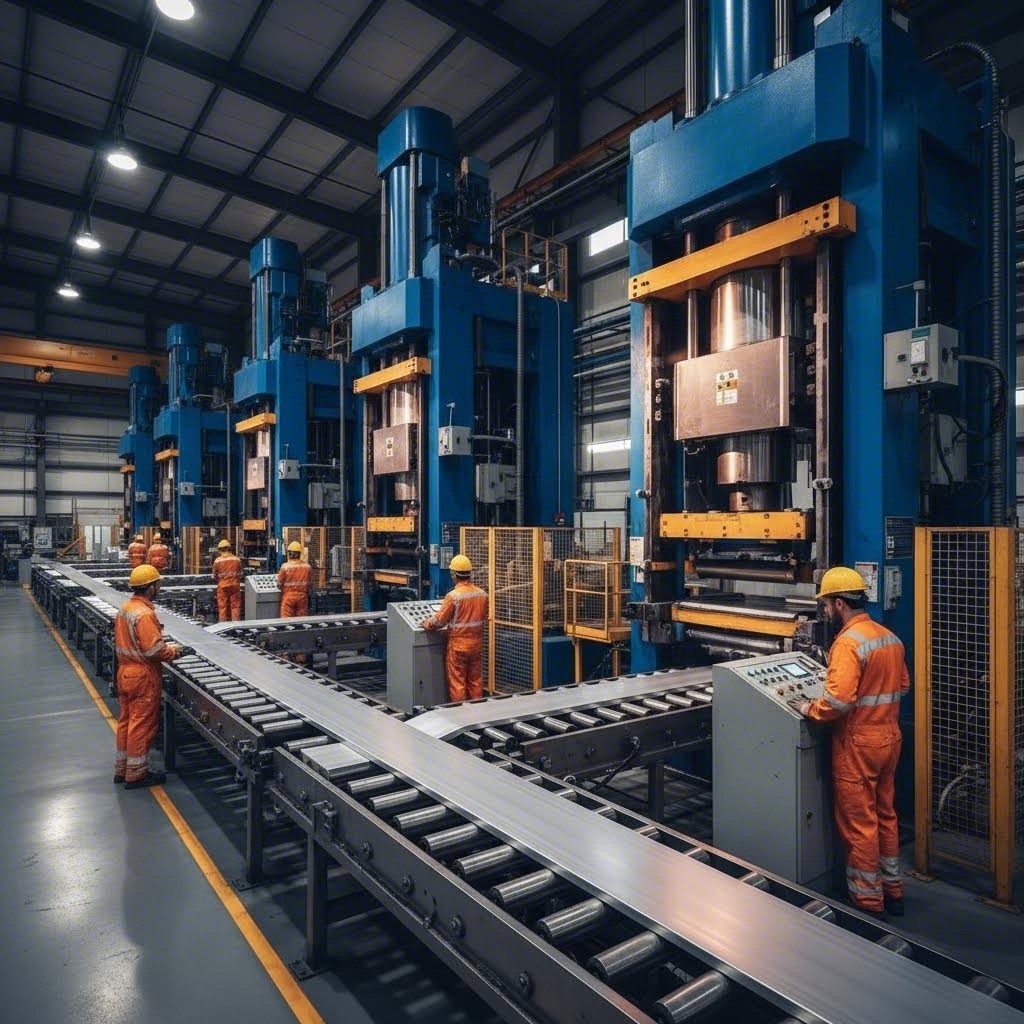
You've mastered wall thickness principles, understood die constraints, selected the right alloy, and verified your design against common failure modes. Now comes the moment of truth: transforming your carefully developed aluminum extrusion design into physical profiles ready for your application. This transition from concept to production is where theory meets reality, and where your choice of manufacturing partner becomes critically important.
Throughout this guide, we've emphasized that design decisions made early have the greatest impact on cost and quality. The same principle applies to manufacturer selection. Partnering with an experienced extruder before finalizing your design often reveals optimization opportunities that would otherwise remain hidden until production problems emerge.
Let's consolidate the critical principles that will guide your aluminium extrusions from drawing board to finished product:
For complex aluminum extrusions profiles, particularly those pushing design limits with thin walls, multiple hollows, or tight tolerances, early collaboration with your manufacturing partner prevents costly surprises. Experienced die designers can evaluate your geometry against production realities and suggest refinements that improve manufacturability without compromising function.
Consider large aluminium extrusions or specialized applications like aluminum door extrusion profiles. These projects demand manufacturers with appropriate press capacity, die design expertise, and finishing capabilities all under one roof. Fragmented supply chains introduce quality variations and coordination challenges that integrated partners eliminate.
How do you identify a manufacturing partner capable of bringing your design to life? The right extruder offers more than competitive pricing. They provide technical expertise that enhances your design, equipment capacity that matches your profile requirements, and downstream capabilities that deliver finished components ready for assembly.
When evaluating potential partners for al extrusion projects, prioritize these criteria:
For designers seeking a partner that exemplifies these capabilities, Shengxin Aluminium's deep processing services demonstrate what comprehensive extrusion partnership looks like in practice. With over 30 years in the industry and 35 extrusion presses ranging from 600T to 5500T, they handle everything from precision aluminum door extrusion profiles to large structural sections. Their integrated approach includes CNC machining centers for secondary operations and surface treatment options including anodizing in custom colors, powder coating, and PVDF coatings, connecting directly to the finishing considerations we discussed earlier.
What distinguishes truly capable partners is their willingness to engage during design development rather than simply quoting finished drawings. When you share preliminary designs with experienced extruders, their feedback often identifies opportunities to:
This collaborative approach transforms the manufacturer relationship from transactional to strategic. Rather than simply executing your design, they become invested partners working toward the same goal: profiles that perform excellently while remaining economical to produce.
The best extrusion partnerships begin before the design is finalized, when manufacturer expertise can still shape decisions that determine 90% of your project's ultimate cost and quality.
As you move forward with your next aluminum extrusion project, remember that the guidelines presented throughout this article represent accumulated industry wisdom refined over decades of production experience. Apply them systematically, collaborate early with capable manufacturing partners, and you'll consistently achieve profiles that meet specifications while avoiding the costly die failures that plague poorly designed extrusions.
Your design journey doesn't end when tooling begins. It evolves into an ongoing partnership where production feedback informs future designs, continuous improvement reduces costs over time, and your aluminum extrusion capabilities expand with each successful project.
The most critical factors include wall thickness uniformity (maintaining adjacent ratios below 2:1), corner radii specifications (minimum 0.020" for internal corners), profile symmetry for balanced metal flow, alloy selection matching your structural and surface finish requirements, and circumscribing circle diameter which determines minimum achievable wall thickness. Early collaboration with experienced extrusion partners like Shengxin Aluminium, with their 35 presses ranging from 600T to 5500T, helps optimize these factors before tooling begins.
6063 aluminum is the industry workhorse, offering excellent extrudability, superior surface finish for anodizing, and standard minimum wall thicknesses. It's ideal for architectural and decorative applications. 6061 provides significantly higher tensile strength (38 ksi vs 30 ksi) for structural applications but requires 10-20% thicker walls, produces less refined surface finishes, and extrudes at slower speeds. Choose 6063 when appearance matters and 6061 when structural performance is the priority.
Choose hollow profiles when you need weight reduction without sacrificing strength, internal cable routing channels, enhanced thermal properties, or modular T-slot assembly systems. Hollow sections offer superior moment of inertia relative to their mass. Select solid profiles when maximum load-bearing capacity is essential, budget is constrained (simpler die costs), extensive post-machining is required, or for simple geometric shapes like bars and angles that don't benefit from internal voids.
The costliest mistakes include unbalanced metal flow from dramatic wall thickness variations, sharp internal corners below 0.020" radius that cause die failure, high tongue ratios exceeding 3:1 in semi-hollow sections, tolerance stack-up problems from unnecessarily tight specifications, and asymmetric designs without compensating features. Using a pre-tooling design review checklist and partnering with experienced manufacturers who offer CNC machining and comprehensive surface treatments helps catch these issues early.
Thinner walls require slower extrusion speeds, higher precision tooling, and result in accelerated die wear and increased scrap rates. Wall thickness must meet minimums based on your profile's circumscribing circle diameter—larger profiles require proportionally thicker walls. Maintaining uniform wall thickness ensures even metal flow, prevents warping during cooling, and extends die life. The optimal balance keeps profiles between 0.100 and 3 lbs/ft while avoiding adjacent wall ratios exceeding 2:1.



 serviço on-line
 0086 136 3563 2360
 sales@sxalu.com
 +86 136 3563 2360
 português
 English
 français
 Deutsch
 русский
 español
 العربية
 ไทย
 Việt
 Українська