
Ever wondered how much weight can aluminum hold when you're building a machine frame or workstation? You're not alone. The 4040 aluminum extrusion has become the go-to choice for engineers, makers, and industrial designers worldwide—yet its true load-bearing capabilities remain surprisingly misunderstood.
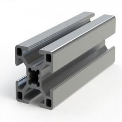
So, what is 4040 exactly? This versatile profile refers to a T-slot aluminum extrusion with cross-sectional dimensions of 40mm x 40mm (or approximately 4 cm x 40 mm in metric shorthand). The square profile makes it one of the most balanced options in the modular framing world, offering excellent strength-to-weight ratios while remaining easy to work with.
The 4040 extrusion belongs to the T-slot family of aluminum profiles—a system that revolutionized modular construction. Imagine building with industrial-grade LEGOs, where every piece connects seamlessly using standardized slots and fasteners. That's the beauty of this system.
Each 4040 aluminum extrusion features T-shaped slots running along its length on one or more sides. These slots accept specialized hardware like T-nuts, bolts, and brackets, allowing you to create custom frames without welding or drilling. The 40mm x 40mm dimension strikes a sweet spot between the lighter 2020 profiles (20mm x 20mm) and heavier 8080 profiles (80mm x 80mm), making it suitable for a remarkably wide range of applications.
You'll find these profiles in CNC machine frames, 3D printer enclosures, industrial workbenches, conveyor systems, and protective guarding. Their popularity stems from three key advantages: structural versatility, ease of modification, and predictable engineering properties.
Here's what many suppliers won't tell you upfront: the 4040 aluminum extrusion weight capacity isn't a single number. It varies dramatically based on how you use the profile. A beam spanning 500mm will support far more weight than the same profile spanning 2000mm. Similarly, a vertical column behaves completely differently than a horizontal beam.
Understanding these fundamentals prevents costly mistakes. Underestimate the load requirements, and you risk structural failure. Overestimate them, and you'll waste money on unnecessarily heavy profiles.
Several critical factors determine how much load your 4040 extrusion can safely handle:
Throughout this guide, you'll discover exactly how these factors interact and learn practical methods for calculating safe working loads. Whether you're designing a lightweight equipment enclosure or a heavy-duty machine base, understanding these principles ensures your project succeeds from the first bolt to the last.
Now that you understand the basics, let's dive into the numbers that actually matter. When engineers calculate whether a 4040 aluminium extrusion can handle your specific load, they're not guessing—they're using precise geometric properties that define exactly how the profile will behave under stress.
Sounds complex? It doesn't have to be. Think of these properties as the profile's "DNA"—fixed characteristics that determine its strength potential. Once you understand what they mean, you'll never look at aluminum extrusion dimensions the same way again.
The moment of inertia (often written as "I" or "Ix/Iy") measures how well a profile resists bending. Imagine trying to bend a ruler flat versus on its edge—same material, dramatically different resistance. That resistance is what moment of inertia quantifies.
For 4040 extrusion dimensions, you'll encounter two values:
Since the 4040 profile is square (40mm x 40mm), Ix and Iy are typically equal—a significant advantage when you need consistent performance regardless of orientation.
The section modulus (often noted as "S" or "Z") tells you how efficiently the profile handles bending stress. Higher section modulus values mean the profile can support greater loads before reaching its stress limits. Engineers use this property directly in beam calculations to determine maximum allowable loads.
Based on manufacturer specifications, here are the typical engineering properties for standard 4040 profiles:
| Profile Variant | Section Modulus (cm³) | Moment of Inertia (cm⁴) | Typical Weight (kg/m) |
|---|---|---|---|
| 4040 Light (PS4040L-8) | 4.1 | 8.2 | ~1.2 |
| 4040 Standard (PS4040-8) | 4.9 | 9.9 | ~1.5 |
| 4080 (for comparison) | 9.5 / 18.4 | 19.1 / 73.7 | ~2.4 |
Data sourced from PB Aluminum profile specifications
Notice the significant difference between the light and standard 4040 4040 variants. That additional 0.8 cm³ of section modulus translates to roughly 20% more load-bearing capability—a critical distinction when you're operating near capacity limits.
Beyond moment of inertia and section modulus, several other cross-sectional properties influence how your 4040 profile performs:
The standard 4040 profile typically features an 8mm slot width, as noted in the physical properties specifications. This slot dimension is critical because it determines which fasteners and accessories are compatible with your build.
Here's how these properties translate to real-world performance: a standard 4040 profile with a moment of inertia of 9.9 cm⁴ can support approximately 1,324 N (135 kgf) as a concentrated center load at a 500mm span, according to allowable load calculations assuming L/1000 deflection limits. Extend that span to 1,000mm, and capacity drops to around 321 N (33 kgf)—less than a quarter of the shorter span's capability.
The material properties also play a crucial role. Most 4040 profiles use 6063-T5 or 6063-T6 aluminum alloy, which offers:
Where can you verify these specifications for your specific project? Always request the manufacturer's technical data sheet, which should include detailed cross-sectional properties, material certification, and allowable load tables. Reputable suppliers publish this information openly—if a supplier can't provide engineering specifications, consider that a red flag.
With these fundamental properties established, the next critical question becomes: how does the orientation of your profile affect its actual load capacity in your application?
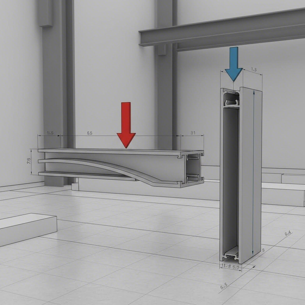
Here's a secret that separates experienced engineers from beginners: the same 4040 profile can have wildly different load capacities depending on how you mount it. A horizontal beam supporting a shelf behaves completely differently than a vertical column holding up a frame. Yet most suppliers quote a single "load capacity" number as if orientation doesn't matter.
It matters enormously. Understanding this distinction could mean the difference between a rock-solid structure and an unexpected failure. Let's break down exactly how mounting orientation transforms your profile's performance.
When you use a 4040 profile as a horizontal beam—think shelf supports, crossbars, or spanning members—two factors limit how much weight it can handle:
Imagine placing a weight in the center of a horizontal beam. The top surface compresses while the bottom surface stretches. This bending creates internal stress that increases with heavier loads and longer spans. Exceed the material's yield strength, and permanent deformation—or failure—occurs.
But here's what many people miss: deflection often becomes the limiting factor before stress does. A beam might be structurally sound yet sag enough to cause problems. For precision equipment, you might limit deflection to L/360 (span length divided by 360). For general applications, L/200 is often acceptable. An 8020 deflection calculator or similar tool can help you verify these limits for your specific setup.
The type of load also dramatically affects capacity:
For a standard 4040 profile used as a horizontal beam with a center point load, approximate capacities based on typical engineering properties look like this:
| Span Length (mm) | Center Point Load Capacity (N) | Center Point Load Capacity (kgf) | Deflection at Capacity (mm) |
|---|---|---|---|
| 300 | ~2,200 | ~224 | 0.3 |
| 500 | ~1,300 | ~133 | 0.5 |
| 750 | ~580 | ~59 | 0.75 |
| 1,000 | ~320 | ~33 | 1.0 |
| 1,500 | ~140 | ~14 | 1.5 |
Values are approximate and assume L/1000 deflection limits with standard 4040 profiles. Actual capacities vary by manufacturer and alloy.
Notice the pattern? Double the span length, and capacity drops by roughly 75%. This inverse relationship catches many designers off guard. If you're working with 8020 extrusion or similar T-slot profiles, the same principles apply—always verify span-specific load ratings rather than assuming a universal capacity number.
Vertical columns play by different rules entirely. When you load a 4040 profile as an upright column, bending stress and deflection become secondary concerns. Instead, a phenomenon called buckling becomes your primary enemy.
Picture pressing down on a thin ruler standing vertically. At some critical load, it suddenly bows outward and collapses—that's buckling. It happens abruptly, often without warning, and well before the material reaches its yield strength.
Engineers use Euler's buckling formula to predict when columns will fail:
Critical buckling load depends on the column's length, cross-sectional properties, and how the ends are supported—not just material strength.
The formula reveals something counterintuitive: a column's buckling resistance decreases with the square of its length. Double the column height, and buckling capacity drops to one-quarter. This makes tall, slender columns particularly vulnerable.
End conditions also dramatically affect performance. A column with both ends fixed (bolted rigidly) can support approximately 4 times more load than the same column with both ends pinned (free to rotate). Real-world connections typically fall somewhere between these extremes.
For 4040 profiles used as vertical columns, here's how capacity changes with height:
| Column Height (mm) | Axial Load Capacity - Fixed Ends (N) | Axial Load Capacity - Pinned Ends (N) |
|---|---|---|
| 500 | ~45,000 | ~11,000 |
| 750 | ~20,000 | ~5,000 |
| 1,000 | ~11,000 | ~2,800 |
| 1,500 | ~5,000 | ~1,200 |
| 2,000 | ~2,800 | ~700 |
Approximate values for standard 4040 profiles. Actual capacity depends on specific profile geometry, alloy, and connection rigidity.
Compare these numbers to the horizontal beam table above. At short spans, vertical columns can handle significantly more load than horizontal beams—often 4 T (40,000+ N) or more for properly supported columns under 500mm. But as height increases, buckling rapidly erodes this advantage.
Several strategies help maximize column performance:
Understanding these orientation-dependent behaviors helps you make smarter design decisions. A 2020 aluminum extrusion strength might suffice for short vertical supports, while the same application as a horizontal span might demand 4040 or larger. The profile hasn't changed—only how physics acts upon it.
With orientation fundamentals covered, you might be wondering: what about different 4040 profile variants? Not all 4040s are created equal, and the differences affect exactly how these calculations apply to your specific project.
Not all 40x40 aluminum extrusion profiles are created equal. Walk into any supplier's catalog, and you'll find multiple 4040 variants—each with different wall thicknesses, slot configurations, and load capacities. Choosing the wrong one could leave your frame dangerously undersized or unnecessarily expensive.
Here's where things get interesting. The 40 series aluminum extrusion family includes light, standard, and heavy-duty options, plus variations in how many slots run along each face. These differences might seem minor on paper, but they translate to significant real-world performance gaps. Let's break down exactly what separates these variants and when each makes sense for your project.
The distinction between standard and heavy-duty 4040 profiles comes down to one primary factor: wall thickness. Heavy-duty versions feature thicker internal walls and reinforced corner sections, which directly increase moment of inertia and section modulus—the properties that determine load capacity.
Think of it like comparing a standard cardboard box to one with reinforced corners. Same external dimensions, dramatically different strength. A heavy-duty aluminum slot 4040 profile might weigh 30-50% more than its standard counterpart, but it can handle proportionally higher loads.
Here's how the main 4040 variants compare:
| Profile Variant | Approximate Weight (kg/m) | Relative Strength Rating | Best Use Cases |
|---|---|---|---|
| 4040 Lite | 1.0 - 1.2 | ★★☆☆☆ | Light enclosures, protective guarding, display frames |
| 4040 Standard | 1.4 - 1.6 | ★★★☆☆ | Workstations, 3D printer frames, general-purpose structures |
| 4040 Heavy-Duty | 1.8 - 2.2 | ★★★★☆ | Machine bases, conveyor supports, high-load applications |
| 4060 Aluminum Extrusion | 1.8 - 2.0 | ★★★★☆ (one axis) | Directional loads, tall frames needing lateral stiffness |
| 4080 Profile | 2.3 - 2.6 | ★★★★★ | Heavy machinery, long spans, industrial automation |
Weights and ratings are approximate; verify with manufacturer specifications for your specific profile.
The lite versions save weight and cost but sacrifice roughly 20-30% of load capacity compared to standard profiles. They're perfect when you're building enclosures or frames that won't see significant structural loads—think safety guarding or aesthetic covers rather than weight-bearing members.
Heavy-duty 4040 profiles fill the gap between standard 4040 and larger 4080 profiles. When should you choose heavy-duty over upgrading to 4080? Consider these factors:
However, when your load requirements push heavy-duty 4040 near its limits, upgrading to 4080 or even 8080 profiles typically makes more engineering sense. Larger profiles offer disproportionately higher strength gains due to their increased moment of inertia—remember, this property scales with the cube of the profile's depth.
Beyond wall thickness, slot configuration significantly affects how much weight your 4040 extrusion can handle. Every T-slot cut into the profile removes material that would otherwise contribute to structural strength.
Common configurations include:
A single-slot 4040 profile can offer 10-15% higher load capacity than its quad-slot equivalent. This difference becomes meaningful in high-load applications or when operating near capacity limits.
Here's a practical decision framework: if your design requires connections on all four faces, the quad-slot configuration is worth the modest strength reduction. But if you only need slots on two faces—say, for a horizontal beam connecting to vertical uprights—choosing a dual-slot variant provides free structural improvement at no additional cost.
When selecting variants, also consider asymmetric profiles like the 4060 aluminum extrusion. These rectangular sections (40mm x 60mm) offer significantly higher strength in one axis while maintaining the 40mm dimension in the other. They're particularly valuable for tall frames where lateral stiffness matters more than front-to-back strength, or for long horizontal spans needing extra rigidity.
The bottom line? Profile selection isn't just about the 40x40 dimension—it's about matching the specific variant to your load requirements, connection needs, and budget constraints. With so many options available, there's almost always a 4040 variant that fits your application perfectly.
Now that you understand profile variants and their relative strengths, the next step is learning exactly how to calculate the weight capacity for your specific span and load configuration.
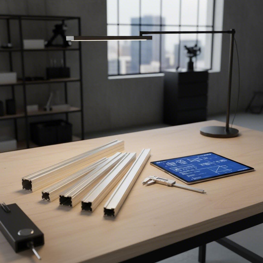
You've seen the engineering properties, understood orientation effects, and compared profile variants. Now comes the question everyone really wants answered: how do you actually calculate whether your 4040 profile can handle your specific load?
This is where most resources fail you. They'll throw out impressive-sounding numbers like "500kg capacity" without mentioning the critical context—that number only applies under very specific conditions. A 4040 beam supporting 500kg across a 200mm span is completely different from attempting the same load across 1,500mm.
Let's fix that gap with a practical methodology you can apply to any project.
Whether you're designing a workbench, machine frame, or equipment enclosure, follow this systematic approach to determine safe working loads:
Sounds complex? Here's a simplified approach for quick estimates. Most manufacturers publish allowable load tables that have already done this math for you. Look for tables showing load capacity at various span lengths, and you'll get practical numbers without running calculations yourself. The 80 20 10 series documentation, for example, provides comprehensive load charts for their full profile range.
For those comfortable with calculations, many CAD programs and online tools can automate beam analysis. An 8020 dimensions reference combined with a simple beam calculator gives you accurate results in minutes. Just ensure you're inputting the correct moment of inertia value for your specific profile variant.
Here's something that trips up even experienced designers: a beam can be structurally sound yet functionally failed if it deflects too much. Deflection limits aren't about preventing catastrophic collapse—they're about maintaining acceptable performance.
Different applications demand different standards:
| Application Type | Typical Deflection Limit | What This Means |
|---|---|---|
| General framing | L/200 | 5mm deflection allowed per 1,000mm span |
| Workstations and benches | L/250 | 4mm deflection allowed per 1,000mm span |
| CNC machines and precision equipment | L/360 | 2.8mm deflection allowed per 1,000mm span |
| Optical tables and measurement systems | L/500 or stricter | 2mm or less per 1,000mm span |
| Ultra-precision applications | L/1000 | 1mm deflection allowed per 1,000mm span |
The "L" in these ratios represents span length. So L/360 for a 720mm span means maximum acceptable deflection is 2mm (720 ÷ 360 = 2). Exceed this limit, and your precision CNC router might produce wavy cuts, or your measurement equipment could give inconsistent readings.
For most 4040 applications, L/200 provides adequate performance. However, if you're building equipment where positioning accuracy matters—3D printers, laser cutters, camera gantries—err toward L/360 or stricter. The extra rigidity costs nothing when factored into initial design but becomes expensive to retrofit later.
You've probably seen claims that 4040 aluminum extrusion can support 500kg. Is this true? The honest answer: it depends entirely on how you're loading it.
Let's run the numbers for context:
The takeaway? Claims about maximum load capacity are meaningless without span context. When someone asks "how much weight can a 4040 hold?" the only correct answer is: "How long is your span, and where is the load positioned?"
For practical design work, start with conservative assumptions. Use the lower capacity values from manufacturer tables, apply your safety factor, and verify that deflection stays within acceptable limits. If calculations show you're operating above 50% of rated capacity for critical members, consider upgrading to heavy-duty 4040 or larger profiles.
With calculation methods now in your toolkit, the next question becomes: how do frame design elements like bracing and connections affect the overall load capacity of your assembly?
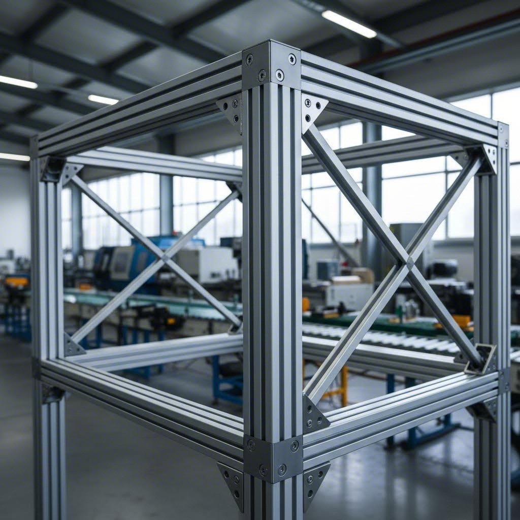
Here's what most suppliers won't tell you: your aluminum extrusion 4040 profile is rarely the weakest link in your frame. The connections are. You could use the beefiest heavy-duty 4040 available, but if your corner brackets can only handle half the load, that's your actual capacity limit.
Understanding how frame design elements affect overall strength transforms you from someone who builds adequate structures into someone who builds optimized ones. The difference? Proper bracing and connection strategies can multiply your frame's effective load capacity by 200% or more—without upgrading a single profile.
Imagine a simple rectangular frame made from 4040 profiles. Push on one corner, and the whole structure wants to parallelogram—shifting out of square under relatively modest force. Now add diagonal bracing across that same frame. Suddenly, the same push barely registers. What changed?
Bracing converts bending forces into axial tension and compression—load types that aluminum extrusion handles exceptionally well. A diagonal brace essentially "triangulates" your frame, and triangles are inherently rigid shapes that resist deformation.
Strategic bracing placement can increase frame rigidity by 300-400% compared to unbraced designs. Here's how different bracing approaches compare:
When should you add bracing? Consider these triggers:
The 8020 t slot system and similar aluminum extrusion 80 20 product lines offer dedicated bracing components designed specifically for T-slot frames. These pre-engineered solutions often outperform improvised bracing because they're optimized for the connection geometry.
Your frame's true capacity is only as good as its weakest connection. This principle catches many designers off guard. They calculate profile strength meticulously, then bolt everything together with undersized hardware and wonder why the assembly feels "soft."
Connection strength depends on three factors: the fastener type, the hardware quality, and the installation technique. Get all three right, and your connections approach the profile's inherent strength. Miss any one, and you've created a weak point.
Common connection options for t slot 8020 and 4040 frames include:
| Connection Type | Typical Shear Capacity (N) | Installation Complexity | Adjustability |
|---|---|---|---|
| Single T-nut + M8 bolt | 2,000 - 3,000 | Low | High |
| Standard corner bracket | 1,500 - 4,000 | Low | Moderate |
| Heavy-duty corner bracket | 5,000 - 8,000 | Moderate | Moderate |
| Gusset plate (4-bolt) | 8,000 - 12,000 | Moderate | Low |
| Hidden anchor connector | 3,000 - 5,000 | High | Low |
Capacities are approximate and vary by manufacturer, material, and installation quality.
Here's a critical detail: bolt torque matters enormously. An M8 bolt torqued to specification (approximately 20-25 Nm for most T-slot applications) develops far more clamping force than one merely "hand tight." Under-torqued connections can have 50% or less of their rated capacity. Always use a torque wrench for structural connections.
Every load capacity number you've seen in this article represents a theoretical maximum—the point where failure becomes likely. Designing to these limits would be reckless. Safety factors provide the margin that keeps your structures safe when real-world conditions deviate from ideal assumptions.
Industry-standard safety factors for aluminum extrusion frames:
The complete system—profile, connections, and frame geometry—determines actual load capacity, not the profile alone.
When you're uncertain about load conditions, round up your safety factor. The cost difference between adequate and overbuilt connections is typically minimal, while the consequences of failure can be severe. A few extra corner brackets or larger bolts provide cheap insurance.
With bracing and connection fundamentals now clear, let's explore how these principles apply across different real-world applications—from machine frames to workstations.
You've mastered the theory—now let's see how 4040 aluminum profiles perform in the real world. Whether you're building a CNC router frame, assembling a production workstation, or designing protective guarding, understanding which applications suit 4040 (and which don't) saves you from costly redesigns.
The truth is, 4040 extruded aluminum handles an impressive range of applications. But it's not always the right choice. Sometimes 2020 aluminum extrusions offer more than enough strength at lower cost. Other times, you'll need to step up to 4080 or 80x40mm profiles to meet demanding load requirements. Let's explore where 4040 shines—and where you should consider alternatives.
Machine frames represent one of the most demanding applications for 4040 aluminum profiles. CNC routers, laser cutters, and 3D printers all require frames that remain rigid under operational stress while minimizing vibration transfer.
For CNC machine frames, 4040 aluminum works exceptionally well for small to medium-sized builds—typically machines with working envelopes under 600mm x 600mm. The profile provides adequate stiffness to resist cutting forces while keeping the overall machine weight manageable. Larger CNC builds often benefit from upgrading to 4080 or 8080 profiles, particularly for the gantry crossbeam where deflection most directly affects cutting accuracy.
3D printer enclosures present a different challenge. Here, the frame primarily supports the enclosure panels and maintains dimensional stability rather than resisting significant external forces. Standard 4040 is often overkill for basic enclosures—2020 aluminum extrusions can handle most printer enclosure applications while saving cost and space. Reserve 4040 for larger enclosures exceeding 500mm cubed or when mounting heavy accessories like filtration systems or heated chamber components.
Protective guarding and safety enclosures follow similar logic. When the primary function is keeping personnel away from moving equipment, standard 4040 provides ample strength for most span lengths under 1,000mm. However, guarding that must withstand impact—such as barriers around forklifts paths or robotic work cells—demands careful load analysis and often benefits from heavy-duty 4040 or larger profiles.
Industrial workstations showcase 4040's versatility perfectly. Adjustable-height benches, tool hanging systems, and modular assembly stations all benefit from the profile's balance of strength, weight, and connection flexibility.
For workbench applications, consider how the load distributes across the frame. A bench surface supporting distributed loads across multiple contact points handles significantly more total weight than one with concentrated point loads. A standard 4040 frame with proper bracing can support workbench surfaces holding 200-400 kg of distributed load comfortably—more than adequate for most assembly operations.
Conveyor systems introduce dynamic load considerations that static calculations don't capture. Moving products create inertia forces, and drive motors generate vibration. These factors mean conveyor frames typically require 25-50% additional capacity margin compared to equivalent static loads. For light-duty conveyors handling products under 25 kg, 4040 aluminum works well. Heavier conveyors or those with rapid acceleration/deceleration cycles often justify upgrading to 4080 profiles.
| Application Type | Typical Load Requirements | Recommended Span Limit | Profile Recommendation |
|---|---|---|---|
| 3D Printer Enclosure (small) | Light (under 10 kg panel loads) | Up to 600mm | 2020 sufficient; 4040 for durability |
| 3D Printer Enclosure (large) | Moderate (10-25 kg with accessories) | Up to 800mm | Standard 4040 |
| CNC Router Frame (small) | Moderate to high (cutting forces) | Up to 500mm | Standard 4040 with bracing |
| CNC Router Frame (medium/large) | High (significant cutting forces) | Up to 400mm for 4040 | Heavy-duty 4040 or 4080/8080 |
| Workbench Frame | Moderate (100-300 kg distributed) | Up to 1,000mm | Standard 4040 |
| Heavy-Duty Workstation | High (300-500 kg distributed) | Up to 750mm | Heavy-duty 4040 or 4080 |
| Light Conveyor Support | Dynamic (under 25 kg product weight) | Up to 800mm | Standard 4040 |
| Heavy Conveyor Support | Dynamic (over 25 kg product weight) | Up to 600mm | 4080 or 8080 |
| Protective Guarding (personnel) | Light static | Up to 1,200mm | Standard 4040 |
| Impact-Resistant Guarding | Dynamic/impact loads | Up to 800mm | Heavy-duty 4040 minimum |
Recommendations assume proper bracing and connection design. Verify with manufacturer specifications for your specific profile variant.
The table above references "dynamic" loads several times—but what does this mean practically? Static loads sit still. Dynamic loads move, vibrate, or impact. This distinction fundamentally changes how you approach frame design.
Vibrating equipment—motors, pumps, spindles, pneumatic actuators—introduces cyclical stress that can loosen connections and fatigue materials over time. A frame that holds 500 kg of stationary equipment might fail when that same equipment vibrates during operation. The rule of thumb: apply a 4:1 safety factor minimum for any application involving significant vibration.
Impact loads present even greater challenges. When products drop onto conveyor frames, when carts bump into workstation legs, or when operators lean heavily on equipment surfaces, instantaneous forces can spike well above static levels. Design for peak forces, not average conditions.
When choosing between profile sizes, use this framework:
Selecting the right profile from the start costs far less than retrofitting an undersized frame later. When in doubt, step up one profile size—the modest additional material cost provides significant peace of mind.
With application scenarios now clear, the final question becomes: how do you ensure you're getting quality extrusions that actually deliver the rated performance for load-critical projects?
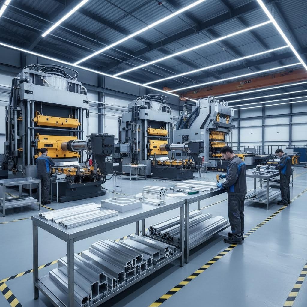
You've calculated your loads, selected your profile variant, and designed your connection strategy. But here's a question that often gets overlooked until problems arise: where are you sourcing your aluminum 4040 extrusion from? The supplier you choose can mean the difference between profiles that meet rated specifications and ones that fall dangerously short.
Not all aluminum extrusions are created equal. Variations in alloy composition, extrusion temperature control, and post-processing quality can produce profiles with significantly different mechanical properties—even when they share identical dimensions. For load-critical projects, partnering with the right manufacturer isn't optional; it's essential.
Choosing an aluminum extrusion supplier involves far more than comparing prices. When your project depends on precise 40 40 aluminum extrusion performance, you need a partner who can deliver consistent quality, detailed engineering data, and responsive technical support.
Start by evaluating the supplier's experience and capabilities. According to industry guidelines from Inquivix Technologies, an experienced supplier brings lessons learned from years of solving complex extrusion challenges. Look for manufacturers with documented track records in your specific application area—whether that's industrial automation, architectural framing, or precision equipment.
Here are the critical criteria for evaluating potential suppliers:
When comparing 8020 extrusion dimensions or 8020 aluminum extrusion dimensions across suppliers, pay close attention to tolerance specifications. A profile advertised as "4040" might have ±0.2mm tolerances from one manufacturer and ±0.5mm from another. For precision assemblies where profiles must mate accurately, tighter tolerances justify premium pricing.
What happens when standard 4040 profiles don't meet your load specifications? You have two options: upgrade to larger standard profiles or explore custom extrusion design. Custom profiles let you optimize strength exactly where needed while maintaining compatibility with your design constraints.
Custom aluminum extrusions can address limitations that standard profiles cannot solve:
The custom extrusion process begins with die development. Experienced manufacturers work with your engineering team to translate load requirements into optimized cross-sectional geometry. This collaboration is where supplier expertise pays dividends—a knowledgeable partner identifies potential issues before tooling investment, saving time and money.
For projects requiring this level of customization, manufacturers like Shengxin Aluminium offer comprehensive end-to-end support. With over 30 years of industry experience and 35 extrusion presses ranging from 600T to 5500T capacity, they handle everything from initial die development through mass production. Their in-house CNC machining centers enable precise cutting, drilling, and bending to exact specifications—critical capabilities when tolerance stack-ups affect assembly fit.
Surface treatment options also matter for load-critical applications. Beyond aesthetics, treatments like anodizing increase surface hardness and corrosion resistance, while powder coating provides additional protection in harsh environments. Quality suppliers offer multiple finish options including standard anodizing, custom colors (champagne, rose gold, and other architectural finishes), PVDF coatings for outdoor applications, and micro-arc oxidation for superior durability.
Not every low-cost supplier delivers acceptable quality. According to industry best practices referenced by aluminum extrusion selection guides, watch for these warning signs:
When evaluating quotes, consider total cost of ownership rather than unit price alone. A supplier with slightly higher pricing but superior tolerances, reliable delivery, and responsive technical support often delivers better overall value. Hidden costs from rework, delays, or failed assemblies quickly erode initial savings from bargain-priced extrusions.
For high-volume production or ongoing partnerships, request sample profiles for testing before committing to large orders. Verify dimensional accuracy, surface finish quality, and material properties against specifications. This upfront verification prevents expensive problems when production scaling begins.
With the right supplier relationship established, you're positioned to execute projects with confidence—knowing that your aluminum extrusion profiles will deliver the performance your calculations predict.
You've now explored everything from engineering fundamentals to real-world applications—and you're equipped with knowledge that many designers learn only through costly trial and error. But before you start ordering profiles, let's distill this information into actionable guidance you can apply immediately to your 40mm aluminum extrusion project.
The most important lesson? There's no single "weight capacity" number for 4040 t slot profiles. Anyone claiming otherwise is oversimplifying complex engineering realities. Your actual capacity depends on how you design, connect, and deploy these versatile profiles.
Throughout this guide, several critical insights emerged that separate successful projects from problematic ones:
Weight capacity depends on the complete system—profile selection, connection strength, frame geometry, and bracing strategy—not the profile alone.
This single principle explains why two seemingly identical frames can have drastically different performance. A well-designed 40 40 aluminium extrusion frame with proper bracing and heavy-duty connections can outperform a poorly designed structure using larger profiles. System thinking trumps component specification every time.
Other essential takeaways include:
Ready to move from theory to practice? Follow this systematic checklist to ensure your 4040 project succeeds from design through assembly:
For standard applications using off-the-shelf profiles, following this checklist typically ensures success. But some projects demand more—custom profile geometries, tighter tolerances, or specialized surface treatments that standard catalogs don't offer.
When your requirements exceed standard specifications, partnering with an experienced manufacturer becomes essential. Companies like Shengxin Aluminium provide end-to-end support from custom die development through mass production, backed by over 30 years of extrusion expertise. Their comprehensive capabilities—including CNC precision machining and advanced surface treatments like anodizing and powder coating—ensure your load-critical applications receive profiles that meet exact specifications.
Whether you're building your first workstation frame or designing complex industrial automation systems, the principles in this guide apply universally. Start with clear requirements, calculate conservatively, connect robustly, and verify against real specifications. Your 4040 aluminum extrusion projects will perform exactly as intended—no surprises, no failures, no costly redesigns.
A standard 4040 aluminum extrusion offers a yield strength of approximately 172 N/mm² (25 ksi) when made from 6063-T5 or 6063-T6 alloy. However, actual load capacity varies dramatically based on application. As a horizontal beam with center point load at 500mm span, it handles roughly 133 kgf. As a short vertical column under 500mm with fixed ends, it can support over 4,500 kgf. The moment of inertia is approximately 9.9 cm⁴ for standard profiles, translating to excellent rigidity for modular frame construction.
Yes, but with important conditions. A 4040 frame can support 500 kg when properly designed. As vertical columns under 300mm height with fixed ends, standard 4040 easily handles this load. For horizontal beams, you need very short spans (150-200mm for center point loads) or distributed loading across 300-400mm spans. The key factors include span length, load distribution, proper bracing, and connection strength. Always apply a minimum 2:1 safety factor for static loads.
The 4040 designation refers to 40mm x 40mm cross-sectional dimensions. Standard profiles feature 8mm slot widths and weigh approximately 1.4-1.6 kg per meter. Variants include lite versions (1.0-1.2 kg/m), heavy-duty options (1.8-2.2 kg/m), and different slot configurations from single-slot to quad-slot. Most 4040 profiles use 6063-T5 or 6063-T6 aluminum alloy with a density of 2.7 g/cm³.
Follow this five-step method: First, measure your unsupported span length between connection points. Second, identify whether loads are concentrated or distributed. Third, apply beam formulas using the profile's moment of inertia (approximately 9.9 cm⁴ for standard 4040). Fourth, verify deflection stays within limits (L/200 for general use, L/360 for precision equipment). Finally, apply safety factors—2:1 minimum for static loads, 4:1 for dynamic applications.
Six critical factors determine load capacity: span length (doubling span cuts capacity by 75%), mounting orientation (horizontal beams vs. vertical columns behave differently), profile variant (lite, standard, or heavy-duty), slot configuration (quad-slot profiles are 10-15% weaker than single-slot), connection methods (brackets often become the limiting factor), and load type (static vs. dynamic). Proper bracing can increase frame rigidity by 200-400%.



 serviço on-line
 0086 136 3563 2360
 sales@sxalu.com
 +86 136 3563 2360
 português
 English
 français
 Deutsch
 русский
 español
 العربية
 ไทย
ไทย Việt
Việt Українська